
Fuel cell device

A fuel cell and conductive layer technology, applied in fuel cells, fuel cell additives, circuits, etc., can solve the problems of improving local reaction conditions and performance, accelerating membrane electrode performance degradation, and improving fuel cell performance and life. The effect of improving design and operating parameters, optimizing performance and life, and improving R&D efficiency

Active Publication Date: 2015-12-16
DONGFANG ELECTRIC (CHENGDU) HYDROGEN FUEL CELL TECH CO LTD
View PDF5 Cites 7 Cited by
  • Summary
  • Abstract
  • Description
  • Claims
  • Application Information

AI Technical Summary

Problems solved by technology

[0006] like Image 6 Shown is the front view of the bipolar plate of the fuel cell (the flow channel is not shown), and the dotted line membrane electrode reaction area is divided into different areas from R1 to R16. Taking this figure as an example for qualitative analysis, the condition of the fuel cell without humidification The relative humidity of R1 at the inlet is the lowest, and the relative humidity of R16 at the outlet is the highest, so the proton exchange membrane at R1 is the driest and the internal resistance of the battery is the largest, resulting in the lowest performance and the fastest decay in this area; Under density operating conditions, due to the increase of generated water, the relative humidity in the R16 area often exceeds 100%, resulting in the accumulation of liquid water in the flow channel, resulting in the inability of the gas to be transported to the surface of the reaction electrode, and accelerating the performance decay of the membrane electrode
[0007] The performance degradation and life attenuation of fuel cells generally first occur in some local areas (such as the above qualitative analysis, not limited to the above analysis), while most other areas maintain good performance and service life. However, these phenomena in Under the conditions of the existing fuel cell device, it cannot be quantitatively measured experimentally (the existing fuel cell can only measure the overall output voltage of the battery under a given current condition), so it is impossible to improve the reaction conditions and performance of the local area purposefully. Significantly improve the performance and life of fuel cells

Method used


Image

  • Fuel cell device
  • Fuel cell device
  • Fuel cell device

Examples


Embodiment Construction

[0047] It should be noted that, in the case of no conflict, the embodiments in the present application and the features in the embodiments can be combined with each other. The present application will be described in detail below with reference to the accompanying drawings and embodiments.

[0048] It should be noted that the terminology used here is only for describing specific implementations, and is not intended to limit the exemplary implementations according to the present application. As used herein, unless the context clearly dictates otherwise, the singular is intended to include the plural, and it should also be understood that when the terms "comprising" and / or "comprising" are used in this specification, they mean There are features, steps, operations, means, components and / or combinations thereof.

[0049] For the convenience of description, spatially relative terms may be used here, such as "on ...", "over ...", "on the surface of ...", "above", etc., to describe...


PUM


Abstract

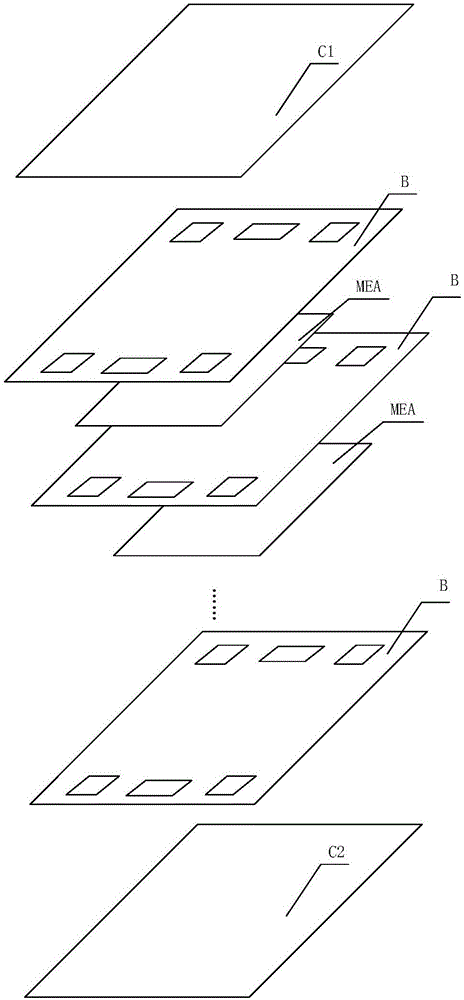
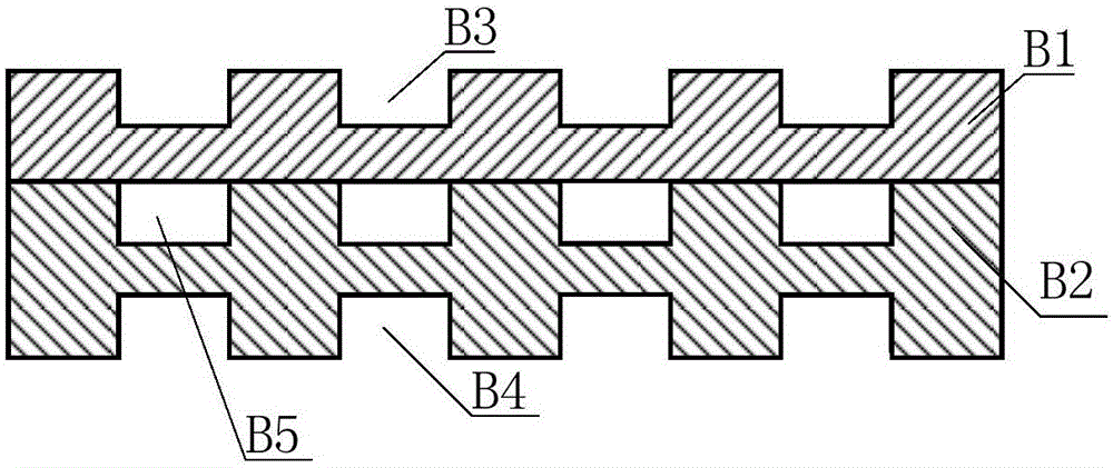
The invention provides a fuel cell device, which comprises a negative collector plate, a negative combined flow field cooling plate, a membrane electrode assembly, a positive combined flow field cooling plate and a positive conducting panel, which are sequentially fitted and connected with one another, wherein the membrane electrode assembly comprises an exchange membrane, a plurality of negative catalyst layers, a plurality of negative gas diffusion layers, a plurality of positive catalyst layers and a plurality of positive gas diffusion layers; the negative collector plate comprises an insulting base body and a plurality of conductive layers; each conductive layer is connected with a collector terminal through a lead; each lead between each conductive layer and each collector terminal is connected with a current sensor in series; the negative combined flow field cooling plate and the positive combined flow field cooling plate are composed of a plurality of sequentially arranged conductive region modules and insulating region modules; and the insulating region modules are arranged between the adjacent conductive region modules. According to the fuel cell device provided by the invention, practical reaction performance distribution and reaction condition distribution of various local regions in the cell can be monitored in real time.

Description

technical field [0001] The invention relates to the field of batteries, in particular to a fuel cell device. Background technique [0002] A fuel cell is an environmentally friendly, high-efficiency, long-life power generation device. Taking the proton exchange membrane fuel cell (PEMFC) as an example, the fuel gas enters from the anode side, the hydrogen atoms lose electrons at the anode and become protons, the protons pass through the proton exchange membrane to the cathode, and the electrons also reach the cathode through the external circuit, and at the cathode Protons, electrons and oxygen combine to form water. The fuel cell converts chemical energy into electrical energy in a non-combustion manner, and its direct power generation efficiency can be as high as 45% because it is not limited by the Carnot cycle. With the battery stack as the core power generation device, the fuel cell system integrates power management, thermal management and other modules, and has the ...

Claims


Application Information

Patent Timeline
Patent Type & Authority Applications(China)
IPC IPC(8): H01M8/04
CPCH01M8/0432H01M8/04492H01M8/04574Y02E60/50
Inventor 殷聪王政温序晖卢毅汤浩
Owner DONGFANG ELECTRIC (CHENGDU) HYDROGEN FUEL CELL TECH CO LTD
Learn More