Supercharge Your Innovation With Domain-Expert AI Agents!

Systems and methods for efficient power generation using a carbon dioxide cycle working fluid

A power generation system and working technology, applied in the direction of machines/engines, gas turbine devices, mechanical equipment, etc., can solve the problems of high power cost, high capital cost, low thermal efficiency, etc., and achieve the goal of reducing physical size and capital cost, and reducing construction cost Effect

Active Publication Date: 2017-05-10
8 RIVERS CAPTTAL LLC
View PDF12 Cites 0 Cited by
  • Summary
  • Abstract
  • Description
  • Claims
  • Application Information

AI Technical Summary

Problems solved by technology

However, this requirement has been shown to be difficult to achieve, since current technologies even for optimal CO 2 Capture design offers only very low thermal efficiency
Additionally, to achieve CO 2 The capital cost of capture is high, and the CO 2 This incurs significantly higher electricity costs compared to systems that discharge into the atmosphere

Method used


Image

  • Systems and methods for efficient power generation using a carbon dioxide cycle working fluid
  • Systems and methods for efficient power generation using a carbon dioxide cycle working fluid
  • Systems and methods for efficient power generation using a carbon dioxide cycle working fluid

Examples


Embodiment 1

[0281] Example 1 Using recycled CO 2 Systems and methods for power generation by combustion of methane from circulating fluids

[0282] A specific embodiment of the system and method according to the present invention is in Figure 11 in the illustration. The following description uses computer simulations to describe the system for a specific cycle under specific conditions.

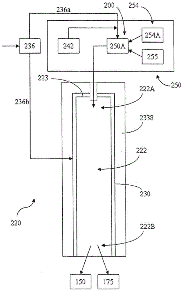
[0283] In this model, methane (CH 4 ) fuel stream 254 with recycled CO 2 Circulating fluid stream 236 is combined in mixer 252 at a temperature of 860° C. and a pressure of 30.3 MPa (and thus it is in a supercritical fluid state) before being introduced into evaporatively cooled combustor 220 . The air separation unit 30 is used to provide concentrated O at a temperature of 105 ° C and a pressure of 30.5 MPa 2 242. The air separation unit also generates heat (Q) which is transferred for use in the process. o 2 242 in combustor 220 with methane fuel stream 254 and CO 2 Circulating fluid 236 comb...

Embodiment 2

[0290] Example 2 Using recycled CO 2 System and method for circulating fluid power generation with pulverized coal power plant retrofit

[0291] Another specific embodiment of the system and method according to the present invention is in Figure 12 in the illustration. The following description uses mathematical simulations to describe the system for a specific cycle under specific conditions.

[0292] This model illustrates the ability to retrofit the systems and methods as described herein for conventional pulverized coal fired power plants.

[0293] O at a pressure of 30.5MPa 2 Stream 1056 together with carbonaceous fuel 1055 (e.g., coal-derived gas illustrated by partial oxidation) at a pressure of 30.5 MPa and CO at a pressure of 30.5 MPa 2 Circulating fluid stream 1053 is introduced into transpiration cooled combustor 220 . The O 2 May be received from an air separator or similar device capable of generating heat (Q) that can be transferred for use in the system, s...

Embodiment 3

[0320] Example 3 Using recycled CO 2 System and method for circulating fluid and multiple expansion steps to generate electricity with methane combustion

[0321] Figure 13 A system and method according to an embodiment of the present disclosure is shown that includes two turbines operating in series with two combustors that burn natural gas using pure oxygen as the oxidant to preheat the inlet to each turbine flow. The presence of the second expansion turbine significantly increases the pressure ratio of the overall turbine system while maintaining virtually the same heat load of the recuperator. The described embodiments also benefit from recirculating high pressure CO by feeding externally generated heat (as described herein) into recuperators at temperature levels ranging from about 150°C to 400°C. 2 Increased efficiency provided in logistics. This additional heat source is the heat of adiabatic compression of the main air compressor in the cryogenic air separation pl...


PUM


Abstract

The present invention provides a method and system for generating electricity using a high efficiency combustor combined with a CO2 circulating fluid. In particular embodiments, the method and system advantageously enable the use of low pressure ratio power turbines and economizer heat exchangers. Additional low-grade heat from an external source can be used to provide some of the heat needed to heat the recirculated CO2 cycle fluid. CO2 derived from fuel can be captured and delivered under pipeline pressure. Capable of trapping other impurities.

Description

technical field [0001] The present invention relates to systems and methods for generating electricity, such as electricity, by using circulating fluids to transfer energy generated through the efficient combustion of fuels. In particular, the systems and methods may use carbon dioxide as the circulating fluid. Background technique [0002] It is estimated that despite the development and use of non-carbon energy sources, fossil fuels will continue to provide most of the world's electricity needs for the next 100 years. However, known methods of burning fossil fuels and / or suitable biomass to generate electricity suffer from increased energy costs and carbon dioxide (CO 2 ) and other emissions create increased problems. Global warming is gaining attention as a potentially catastrophic consequence of increased carbon emissions in both developed and developing countries. Solar and wind power do not appear to be replacing fossil fuel combustion anytime soon, while nuclear po...

Claims


Application Information

Patent Timeline
Patent Type & Authority Patents(China)
IPC IPC(8): F02C1/06F02C3/34F02C6/00
CPCF02C1/06F02C3/34F02C6/003
Inventor R.J.奥勒姆M.R.帕尔默小格伦.W.布朗J.E.费特维特B.A.福里斯特
Owner 8 RIVERS CAPTTAL LLC
Features
  • R&D
  • Intellectual Property
  • Life Sciences
  • Materials
  • Tech Scout
  • Unparalleled Data Quality
  • Higher Quality Content
  • 60% Fewer Hallucinations
Learn More