Artificial structural acoustic field based micro-fluid system and particle control method

A technology of microfluidic system and artificial structure, which is applied in the field of microfluidic system and control particles based on the artificial structure sound field, which can solve the problems of precise control of microbubble groups, unstable microbubbles, uneven size, etc., and achieve fast and flexible switching Effect

Active Publication Date: 2016-01-06
SHENZHEN INST OF ADVANCED TECH CHINESE ACAD OF SCI
View PDF6 Cites 43 Cited by
  • Summary
  • Abstract
  • Description
  • Claims
  • Application Information

AI Technical Summary

Problems solved by technology

However, microbubbles are unstable and non-uniform in size, and it is

Method used


Image

  • Artificial structural acoustic field based micro-fluid system and particle control method
  • Artificial structural acoustic field based micro-fluid system and particle control method
  • Artificial structural acoustic field based micro-fluid system and particle control method

Examples


Embodiment 1

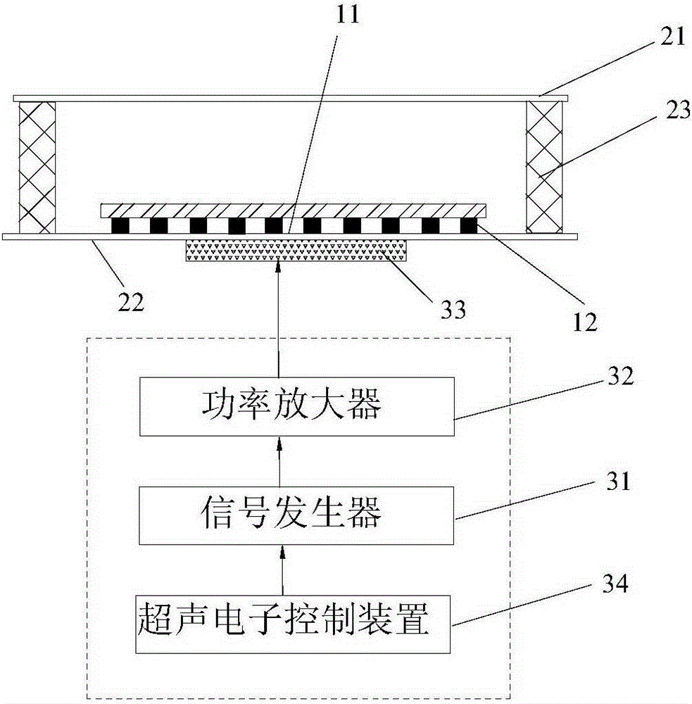
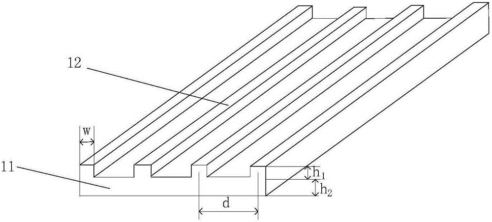
[0059] Such as figure 1 As shown, the microfluidic system based on the artificial structure sound field of the present application, one embodiment thereof, includes a microcavity, an ultrasonic emitting device and a phononic crystal plate, the ultrasonic emitting device is used to emit ultrasonic waves, and the microcavity is used to contain particles containing solution, the phononic crystal plate is placed in the microcavity, and the phononic crystal plate is an artificial periodic structure, which is used to modulate the sound field to manipulate the particles. The particles in this application include micro-nano particles and / or cells, and the phononic crystal plate is specifically used to modulate the sound field to drive the directional transport of the micro-nano particles along the designed path; the phononic crystal plate is used to modulate the sound field to capture and arrange cells to form a cell array, And the phononic crystal plate can also be used to generate m...

Embodiment approach

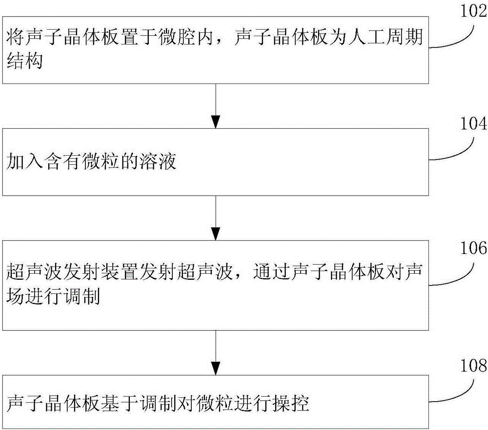
[0068] Such as image 3 As shown, the method of microfluidic manipulation of particles based on the artificial structure acoustic field of the present application, an embodiment thereof, includes the following steps:

[0069] Step 102: placing the phononic crystal plate in the microcavity, the phononic crystal plate is an artificial periodic structure.

[0070] Step 104: Adding the solution containing microparticles.

[0071] Step 106: The ultrasonic emitting device emits ultrasonic waves, and modulates the sound field through the phononic crystal plate.

[0072] Step 108: The phononic crystal plate manipulates the particles based on the modulation.

[0073]Wherein step 108 specifically includes:

[0074] Step 1082: The phononic crystal plate transports micro-nano particles based on the modulated sound field;

[0075] The phononic crystal plate is arranged based on the acoustic radiation force generated by modulating the sound field, trapping cells to form a cell array, an...


PUM

PropertyMeasurementUnit
Heightaaaaaaaaaa

Abstract

The invention discloses an artificial structural acoustic field based micro-fluid system which comprises a micro-cavity and an ultrasonic transmitting device. The micro-cavity is used for containing a particle-containing solution, and the ultrasonic transmitting device is used for transmitting ultrasonic waves. The artificial structural acoustic field based micro-fluid system is characterized by further comprising a photonic crystal slab arranged in the micro-cavity, the photonic crystal slab is of an artificial periodic structure and is used for modulating an acoustic field to control particles. The invention further discloses a particle control method for an artificial structural acoustic field based micro-fluid. In the preferred embodiment of the invention, due to the fact that the micro-fluid system comprises the micro-cavity, the ultrasonic transmitting device and the photonic crystal slab, the ultrasonic transmitting device is used for transmitting the ultrasonic waves and the photonic crystal slab is of the artificial periodic structure and is used for modulating the acoustic field to control particles, a new medicine delivery means is provided, and technical support is provided for research and development of drugs.

Description

technical field [0001] The present application relates to the microfluidic control technology, in particular to a microfluidic system based on an artificial structural acoustic field and a method for manipulating particles. Background technique [0002] Microfluidic chips, also known as Labonachips, have the advantages of miniaturization, integration, high throughput, low energy consumption, and rapid analysis. They have been widely used in biology, chemistry, medicine, and the environment. In the process of microfluidic analysis and detection, micro-nano particles such as cells, DNA, proteins, polystyrene microspheres, and gold nanoparticles need to be transported to functional units such as sample preparation, reaction, separation, and detection through microfluidics. Therefore, precise and fast micro-nanoparticle transport technology provides the necessary power and precise control for microfluidic flow, and is a crucial functional module of microfluidic devices. [0003...

Claims


Application Information

Patent Timeline
IPC IPC(8): B01L3/00C12M1/42B01J19/10
Inventor 郑海荣李飞蔡飞燕孟龙王辰张成祥邱维宝李永川严飞牛丽丽耿刘峰徐超伟
Owner SHENZHEN INST OF ADVANCED TECH CHINESE ACAD OF SCI
Why Eureka
Try Eureka