

Magnetic particle chemiluminescence micro-fluidic chip
A microfluidic chip and chemiluminescent technology, applied in chemical instruments and methods, laboratory utensils, laboratory containers, etc., can solve problems such as incomplete reaction, stop of chip liquid flow, and inability of liquid to fill predetermined channels, etc. Achieve the effect of increasing accuracy and avoiding simple structural design
- Summary
- Abstract
- Description
- Claims
- Application Information
AI Technical Summary
Problems solved by technology
Method used
Image

Examples
Embodiment 1
[0040] Example 1: Microfluidic chip with liquid sensor device
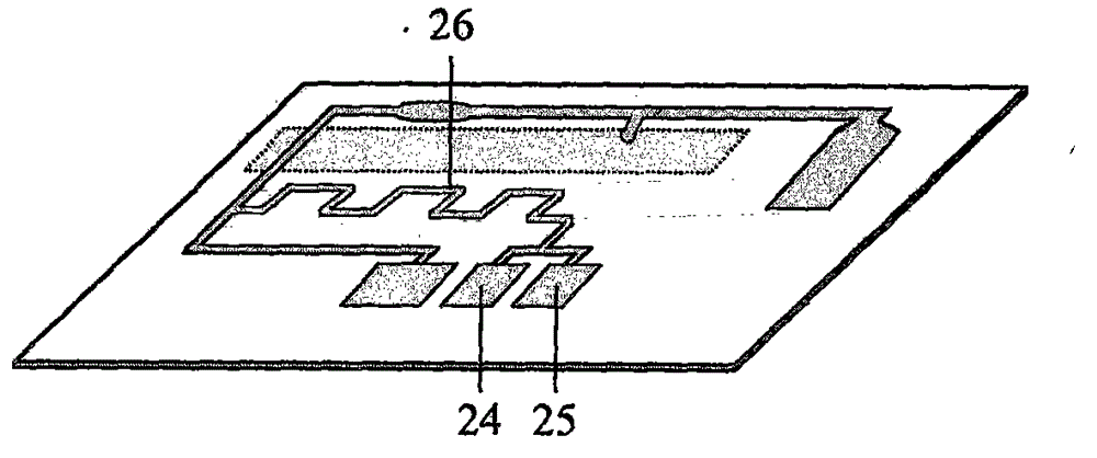
[0041] like Figure 4 Shown is a schematic cross-sectional view of a liquid sensing device used in a microfluidic chip. A conductive needle (31) is inlaid on the microfluidic chip (27), and one end of the contact probe (30) is installed on the supporting circuit board (29), and the other end passes through the metal substrate (28) to connect with the microfluidic chip. contact with exposed conductive pins. The top of the metal substrate is used to carry the microfluidic chip and fix the circuit board, and the supporting circuit board is used to detect the electrical signal on the probe.
[0042] like Figure 5 and Figure 6 As shown, a plurality of conductive needles are inlaid on different positions of the microfluidic chip, all of which are located next to the microchannel through which the liquid passes through the microfluidic chip, and communicate with the microchannel. The conductive needle is made of a...
Embodiment 2
[0046] Example 2: Double-antibody sandwich determination of hypersensitive troponin I (cTnI)
[0047] (1) Antibody labeling
[0048] Dissolve 5 μg of HRP in 1 mL of distilled water, then add 0.2 mL of 0.1 M freshly prepared NaIO4 solution, react in the dark at room temperature for 20 min, and dialyze the purified solution with 1 mM pH 4.4 sodium acetate buffer. Then adjust the pH to 9.0 with 0.2 M pH9.5 carbonate buffer, add 10 μg of anti-cTnI monoclonal antibody, and react at room temperature for 2 h in the dark. Add 0.1 mL of newly prepared 4 mg / mL NaBH4 solution, mix well, and react at 4°C for 2 h. Put the above solution into a dialysis bag, dialyze against 0.15MpH7.4PBS, overnight at 4°C, and obtain HRP-labeled cTnI antibody.
[0049] Add 1mg magnetic particles (2μm in size), 10μg EDC and 15μg NHS solution and 15μg anti-cTnI monoclonal antibody (different from HRP-labeled antibody) solution to 1ml 10mM pH7.4 phosphate buffer, mix well and react at room temperature for 4h...
Embodiment 3
[0060] Example 3: Magnetic Particle Size Screening
[0061] Refer to Example 2 for other experimental conditions, and the magnetic particle size and magnetic induction of the magnet are carried out according to the following scheme.
[0062] The particle size is 0.1 μm, 0.5 μm, 1.8 μm, 2.4 μm, 1 μm, 3 μm, 10 μm. The magnetic induction of the magnet is 500 Gauss, 1000 Gauss, 4000 Gauss, 8000 Gauss, 12000 Gauss. Magnetic particles of seven sizes are driven by these five kinds of magnets respectively.
[0063] The experimental results show that when the 0.1μm magnetic particles are combined with the 500 Gauss magnet, the minimum detection limit is 500pg / ml, the quantitative detection range is 0.5~50ng / ml, and the linear correlation coefficient R 2 >0.95; intra-assay and inter-assay repeatability are less than 20%. That is: the chemiluminescent signal is weak, the sensitivity is not high, and the repeatability is poor.
[0064] When 10μm magnetic particles and 12000 Gauss magn...
PUM
| Property | Measurement | Unit |
|---|---|---|
| Size | aaaaa | aaaaa |
| Magnetic induction | aaaaa | aaaaa |
| Size | aaaaa | aaaaa |
Abstract
Description
Claims
Application Information