Constant-current and constant-frequency inductively coupled transmission system and design method thereof

A technology of inductive coupling and transmission system, which is applied in the direction of control/regulation system, DC power input conversion to DC power output, output power conversion device, etc., which can solve the problems of low safety, poor reliability and high cost

Inactive Publication Date: 2016-01-06
CHINA UNIV OF MINING & TECH
View PDF5 Cites 11 Cited by
  • Summary
  • Abstract
  • Description
  • Claims
  • Application Information

AI Technical Summary

Problems solved by technology

[0005] For the current ICPT system design, in order to keep the load output current constant, the primary resonance current constant and the system resonance operating frequency stable, closed-loop negative feedback control for different control objectives is introduced, resulting in complex system structure, high cost, low safety and In order to solve the problem of poor reliability, the present invention proposes a new composite resonance type inductively coupled power transmission system, which naturally meets the above-mentioned control objectives through system structure design and parameter design, which not only simplifies the system structure, saves system cost, but also improves System Security and Reliability

Method used


Image

  • Constant-current and constant-frequency inductively coupled transmission system and design method thereof
  • Constant-current and constant-frequency inductively coupled transmission system and design method thereof
  • Constant-current and constant-frequency inductively coupled transmission system and design method thereof

Examples


Embodiment Construction

[0019] In order to make the purpose of the present invention, technical solutions and advantages clearer, the present invention will be described in further detail below in conjunction with accompanying drawing:

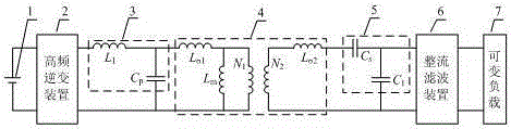
[0020] Such as figure 1 As shown: a constant current constant frequency inductive coupling power transmission system is mainly composed of DC power supply 1, high frequency inverter device 2, primary side reactive power compensation mechanism 3, mutual inductance coupling mechanism 4, secondary side reactive power compensation mechanism 5, rectification and filtering Device 6, variable load 7 constitute.

[0021] The DC power supply 1 generates high-frequency square-wave alternating current through the high-frequency inverter device 2, wherein the high-frequency inverter device 2 adopts a voltage-type full-bridge inverter mode, and the four power switch tubes adopt a 180° complementary conduction mode.

[0022] The high-frequency square-wave alternating current gene...


PUM


Abstract

The invention discloses a constant-current and constant-frequency inductively coupled transmission system and a design method thereof. The system comprises a direct current power supply, a high-frequency inverter, a primary reactive compensation mechanism, a mutual inductance coupling mechanism, a secondary reactive compensation mechanism, a rectifier and filter device and a variable load. The constant-current and constant-frequency inductively coupled transmission system is characterized in that wireless transmission of primary and secondary electric energy is achieved through the mutual inductance coupling mechanism; high-frequency sine alternating current which is picked up by the primary side of the mutual inductance coupling mechanism is rectified and filtered through the rectifier and filter device; the output current is constant; the whole system works in a complete resonant state and does not change along with change of the load; and the power supply requirements of the current-type variable load are met. The constant-current and constant-frequency inductively coupled transmission system has the significant effects that through certain topology designs of primary and secondary reactive compensation mechanisms and a system parameter design, constant outputs of the load current and the primary resonance current of the system under a variable load condition are achieved; the stability of the working frequency of the system is ensured; and the system is simple in overall structure and safe and reliable to work.

Description

technical field [0001] The invention belongs to the field of wireless energy transmission, and in particular relates to a constant current constant frequency inductive coupling transmission system and a design method thereof. Background technique [0002] In recent years, wireless power transmission technology has been developed rapidly, and the products using this technology are increasing. Among them, inductively coupled power transfer (ICPT) technology is a flexible, practical and new wireless power transfer technology based on the principle of electromagnetic induction, which has been widely used in medical, transportation, robotics and oil exploration and other fields. In industrial applications, constant current sources are often used in battery charging, automatic instrument and sensor power supply, and LED drive. [0003] In ICPT system design, in order to improve the system’s ability to carry loads, it is usually required that the current output from the system to ...

Claims


Application Information

Patent Timeline
Patent Type & Authority Applications(China)
IPC IPC(8): H02M3/335H02M1/42
CPCY02B70/10
Inventor 夏晨阳陈国平张杨柳玉玲王卫任思源谷志鹏赖娜王恩同刘海伟
Owner CHINA UNIV OF MINING & TECH
Why Eureka
Try Eureka