
Tower photocatalytic device and catalytic method thereof

A photocatalytic, tower-type technology, applied in the direction of oxidized water/sewage treatment, etc., can solve the problems that restrict the practical application of photocatalytic technology, the difficulty of large-scale synthesis of nano-films, and the difficulty of recycling photocatalysts, etc., to achieve simple structure and low cost , easily controlled effects

Inactive Publication Date: 2016-01-20
SHANGHAI SECOND POLYTECHNIC UNIVERSITY
View PDF5 Cites 2 Cited by
  • Summary
  • Abstract
  • Description
  • Claims
  • Application Information

AI Technical Summary

Problems solved by technology

[0004] 1. In the photocatalytic reaction, continuous stirring is required to make the catalyst contact with the pollutants, otherwise the catalyst will naturally settle to the bottom of the container, which is difficult to achieve in large-scale sewage treatment applications;
[0005] 2. The catalyst is difficult to recycle;
[0006] 3. The photocatalytic sewage treatment technology with agitation / aeration has the disadvantages of small treatment capacity per ton of water, large footprint, and sequential batch operation
These shortcomings restrict the practical application of photocatalytic technology to a certain extent.
[0007] In order to overcome the shortcomings of the photocatalytic process that requires stirring and the photocatalyst is difficult to recycle, Athanasekou et al. prepared TiO 2 Composite nano film with graphene as photocatalytic material to degrade sewage
Although the catalyst is used in the form of a thin film to overcome the shortcomings of powders that are difficult to recycle, but in the large-scale use of photocatalytic degradation of urban sewage, nano-films are difficult to practically apply due to the difficulty of large-scale synthesis

Method used


Image

  • Tower photocatalytic device and catalytic method thereof
  • Tower photocatalytic device and catalytic method thereof

Examples


Embodiment 1

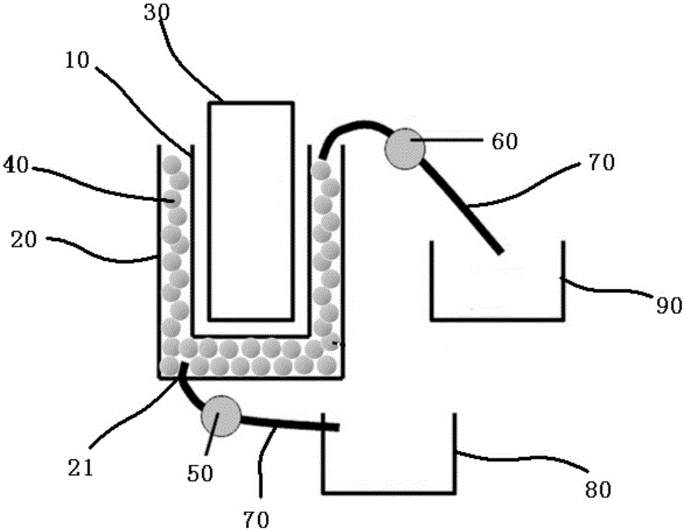
[0029] see figure 1 As shown, the present invention discloses a tower-type photocatalytic device, comprising a cavity with a double-layer structure, a first water pump 50, a second water pump 60, a light source 30 and a control light source, the first water pump, the second water pump The circuit system for the operation of the sump pump.

[0030] The cavity of the present invention is composed of an inner cavity 10 and an outer cavity 20 similar to the structure of a double-layer glass water cup. A light source 30 is arranged in the inner cavity 10, and the light source can be an ultraviolet lamp; the size of the light source and the size of the inner cavity can be determined according to The actual needs to be adjusted, the thickness of the outer cavity 20 is 0.5-3cm; the outer cavity 20 is provided with a block photocatalyst 40 to ensure the catalytic efficiency of the block photocatalyst, on the premise that it can be recycled conveniently, it is recommended The size of t...

Embodiment 2

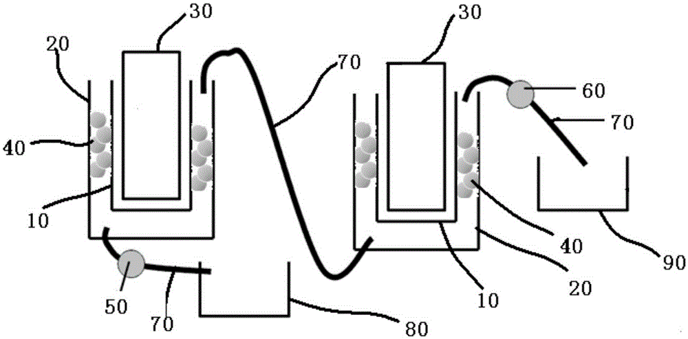
[0034] see figure 2 As shown, the structure and working principle of embodiment 2 are basically the same as embodiment 1, the difference is that, in the case of a large amount of sewage to be treated, there can be multiple cavities, and multiple cavities can be combined during use. The body water pipes are connected in series, and the water pipes in the middle do not need to be powered by pumps.


PUM

PropertyMeasurementUnit
thicknessaaaaaaaaaa

Abstract

The invention discloses a tower photocatalytic device and a catalytic method thereof. The tower photocatalytic device comprises a cavity with a double-layer structure, a first suction pump, a second suction pump and a circuit system, wherein the cavity is composed of an inner cavity and an outer cavity, a light source is arranged in the inner cavity, a block photocatalyst is arranged in the outer cavity, and a water inlet is formed in the bottom of the outer cavity; one end of the first suction pump is connected with the water inlet of the outer cavity through a hose, and the other end of the first suction pump is connected with a sewage pool through a hose; one end of the second suction pump is connected with an opening in the upper end of the outer cavity through a hose, and the other end of the second suction pump is connected with a reservoir through a hose; the circuit system is used for controlling the light source, the first suction pump and the second suction pump to operate, and switches of the circuit system are all installed on the outer side surface of the outer cavity. The preparation method is simple and easy to implement and has the advantage of low cost; the photocatalytic device adopts block catalytic materials, so that the recycling of the catalyst is facilitated, and large-scale treatment can be performed on sewage by using a photocatalytic technique.

Description

technical field [0001] The invention relates to a photocatalytic device, in particular to a tower photocatalytic device and a catalytic method thereof. Background technique [0002] In today's society, environmental pollution has become a global problem that needs to be solved urgently. Photocatalytic technology has gradually attracted widespread attention in the scientific community due to its potential application in environmental purification (R. Quesada-Cabrera, et al., Applied Catalysis B, 2014, 160, 582- 588.). Photocatalytic technology refers to the separation of electrons and holes inside the photocatalytic material under the irradiation of ultraviolet light or visible light, and the hydroxyl radical·OH and superoxide ion·O generated on the surface of the catalytic material 2- , hydroperoxy·HO 2 Such active groups can directly oxidize organic matter to CO 2 and H 2 O and other small inorganic molecules (J. Yang, et al., J. Phys. Chem. B, 2005, 109, 21900-21907.)....

Claims


Application Information

Patent Timeline
Patent Type & Authority Applications(China)
IPC IPC(8): C02F1/72
Inventor 张利谢洪勇孙志国
Owner SHANGHAI SECOND POLYTECHNIC UNIVERSITY
Learn More