High-temperature-resistant cementing material system

A technology of high temperature resistance and well cementing, which is applied in the direction of drilling compositions, chemical instruments and methods, etc., can solve the problems of poor high temperature resistance of oil well cement, and achieve the effects of low cost, reduced environmental pollution, and reliable technology

Active Publication Date: 2016-01-20
CHINA UNIV OF PETROLEUM (EAST CHINA)
View PDF3 Cites 9 Cited by
  • Summary
  • Abstract
  • Description
  • Claims
  • Application Information

AI Technical Summary

Problems solved by technology

[0005] The purpose of the present invention is to provide an environment that can utilize high temperature and high pressure in deep formations, through the hydrothermal synthesis reaction of different silicon, calcium, aluminum and other oxygen-containing compounds and water solvents under high temperature and high pressure conditions, to form a composite material with good compressive strength High temperature resistant silicate and aluminosilicate cementation products, so as to effectively cement and isolate deep oil and gas wells, and solve the problem of poor high temperature resistance of oil well cement

Method used


Image

  • High-temperature-resistant cementing material system
  • High-temperature-resistant cementing material system
  • High-temperature-resistant cementing material system

Examples


Embodiment 1

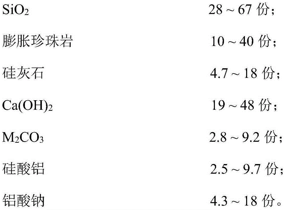
[0027] Example 1: Composition of high temperature resistant cementing material system

[0028] A high-temperature-resistant cementing material system can be composed of the following oxygen-containing compounds such as silicon, calcium, and aluminum, and the mass parts of each substance are specifically: SiO 2 42.2 parts, expanded perlite 13.5 parts, wollastonite 5.7 parts, Ca(OH) 2 22.3 parts, Li 2 CO 3 4.5 parts for aluminum silicate, 2.7 parts for aluminum silicate, and 9.1 parts for sodium aluminate.

Embodiment 2

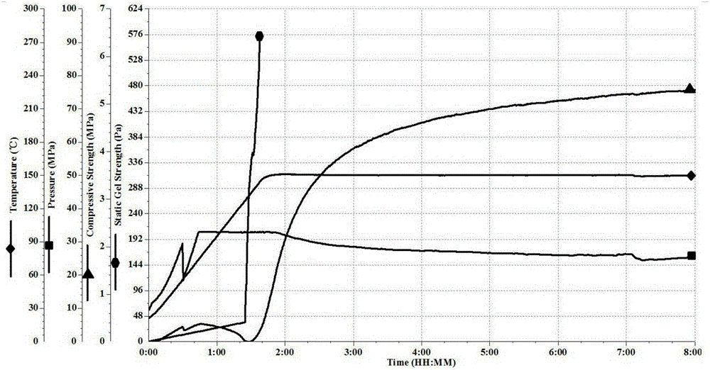
[0029] Example 2: Performance test of high temperature resistant cementing material system slurry

[0030] Taking the high temperature resistant cementing material system in Example 1 as the test object, first weigh and mix the solid dry ash component and the liquid water component of the high temperature resistant cementing material system for slurry preparation, and then mix them according to the standard GB / T19139- 2003 "Oil well cement test method" to prepare slurry. The test results are shown in Table 1.

[0031] Table 1. Slurry properties of high temperature resistant cementing material system

[0032] Numbering

Embodiment 3

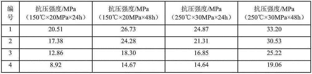
[0033] Example 3: Compressive Strength Test of High Temperature Resistant Cementing Material System

[0034] Taking the high-temperature cementing material system in Example 1 as the test object, first weigh and mix the solid dry ash component and the liquid water component of the high-temperature cementing material system for slurry preparation, and then press the standard GB / T19139-2003 " Oil well cement test method "Prepare slurry, measure compressive strength after high temperature and high pressure curing, test results are shown in Table 1.

[0035] Table 2 Compressive strength performance of high temperature resistant cementing material system

[0036]


PUM

PropertyMeasurementUnit
densityaaaaaaaaaa
particle diameteraaaaaaaaaa
densityaaaaaaaaaa

Abstract

The invention provides a high-temperature-resistant cementing material system which mainly solves the problems that in existing oil well cement, the high-temperature strength is declined and the high-temperature mechanical stability is poor and is suitable for the field of high-temperature cementing of oil gas wells. The high-temperature-resistant cementing material system is prepared from, by mass, 28-67 parts of SiO2, 10-40 parts of expanded perlite, 4.7-18 parts of wollastonite, 19-48 parts of Ca(OH)2, 2.8-9.2 parts of M2CO3, 2.5-9.7 parts of aluminum silicate and 4.3-18 parts of sodium aluminate. The high-temperature-resistant cementing material system can meet well cementing operation in deep formation under the high-temperature high-pressure conditions and has the advantages of being convenient to construct on site and low in cost; in addition, compared with the process of producing oil well cement, the CO2 emission load can be significantly decreased, and the application prospect is wide.

Description

technical field [0001] The invention relates to a high temperature resistant cementing material system for oil and gas wells, in particular to a high temperature resistant cementing material system suitable for deep oil and gas well sections. Background technique [0002] my country is rich in deep oil and gas resources, in the Paleozoic in the east of my country, the Middle Paleozoic in the sea, the Lower Paleozoic in the south, the Paleozoic in the northwest, especially the Lower Paleozoic in the Tarim Basin, the Junggar Basin-Qaidam The oil and gas resources in deep areas such as the Basin-Hexi Corridor and the Upper Paleozoic in Northeast China are very rich. Therefore, accelerating the exploration and development of deep oil and gas resources has become an important task of oil and gas development in my country. With the exploration and development of deep oil and gas resources, the drilling depth is getting deeper and deeper, and the cementing of oil and gas wells is f...

Claims


Application Information

Patent Timeline
Patent Type & Authority Applications(China)
IPC IPC(8): C09K8/467
CPCC09K8/467
Inventor 王成文徐伟祥孟凡昌王瑞和
Owner CHINA UNIV OF PETROLEUM (EAST CHINA)
Why Eureka
Try Eureka