Light receiving circuit

A light-receiving circuit, photodiode technology, applied in electromagnetic receivers and other directions, can solve the problems of reducing the voltage swing at point F, small voltage swing, large proportion, etc., to achieve low transmission delay time, output waveform optimization, The effect of reducing delay variance

Active Publication Date: 2016-01-20
THE 44TH INST OF CHINA ELECTRONICS TECH GROUP CORP
View PDF12 Cites 3 Cited by
  • Summary
  • Abstract
  • Description
  • Claims
  • Application Information

AI Technical Summary

Problems solved by technology

but, figure 1 The light-receiving circuit shown does not greatly improve the transmission delay time for the following reasons: figure 1 The signal delay of the optical receiving circuit is mainly composed of three parts: first, the signal delay generated by the transimpedance amplifier composed of the operational amplifier Amp05 and the resistor R9, and second, the signal delay generated by the inverting amplifier composed of the resistors R10, R11 and the operational amplifier Amp06 Signal delay, third, the signal delay generated by the output stage composed of resistor R12, output transistor Q and pull-up resistor RL; because the light receiving circuit needs to have a certain fan-out capability, a large-sized output transistor is usually used in the design, resulting in The carrier storage effect in the base region of the output transistor becomes very serious, making the delay caused by the output stage turn-off account for the largest proportion of the total transmission delay time, so, although figure 1 The optical receiving circuit can reduce the transmission delay time of the line before the output stage to a certain extent, but its improvement on the transmission delay time of the entire optical receiving circuit is not significant
[0005] In order to improve the transmission delay time of the optical receiving circuit, those skilled in the art have also proposed figure 2 The light receiving circuit structure shown in the figure uses the voltage at point F to control the opening and closing of the auxiliary transistor Q4, so as to achieve the purpose of auxiliary turning off the output transistor Q3, but the light receiving circuit still exists The following problems: 1) During high-speed data transmission, the input transimpedance amplifier is required to use a low transimpedance value to obtain a large bandwidth, so that the voltage swing at point F is small, especially in the monolithic integrated optical receiving circuit , the sensitivity of the integrated photodiode is much lower than that of a single tube, which further reduces the voltage swing at point F, causing the auxiliary transistor Q4 to fail to turn off; 2) The signal from point F to the base of output transistor Q3 is the same as that from point F to There is a significant time delay in the signal at the base of the auxiliary transistor Q4, such as image 3 As shown, the time delay makes the auxiliary transistor Q4 turn on in advance, thus causing the output transistor Q3 to turn off in advance, which affects the output waveform of the light receiving circuit

Method used


Image

  • Light receiving circuit
  • Light receiving circuit
  • Light receiving circuit

Examples


Embodiment Construction

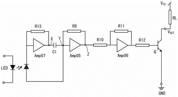
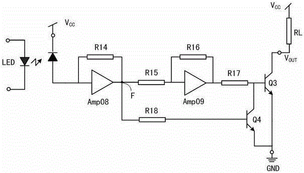
[0023] A light receiving circuit, the structure of which is: the light receiving circuit is composed of 4 operational amplifiers, 8 matching resistors, an output transistor Q1, an auxiliary transistor Q2 and a photodiode G;

[0024] The input terminal of the first operational amplifier Amp01 is connected with the anode of the photodiode G, the output terminal of the first operational amplifier Amp01 is connected with one end of the second matching resistor R2, and the other end of the second matching resistor R2 is connected with the input of the second operational amplifier Amp02 The output terminal of the second operational amplifier Amp01 is connected to one end of the fourth matching resistor R4, and the other end of the fourth matching resistor R4 is connected to the base of the output transistor Q1; the collector of the output transistor Q1 is open, and the output terminal of the output transistor Q1 Emitter grounded;

[0025]The two ends of the first matching resistor R...


PUM


Abstract

Provided is a light receiving circuit, comprising four operational amplifiers, eight coupling resistors, an output triode, an auxiliary triode and a photodiode which are connected according to the scheme to respectively form a main line and an auxiliary line, wherein the main line is used for controlling the turn-on / turn-off of triodes; the auxiliary line is used for rapidly discharging the charge stored on the base electrode of the output triode. The invention provides a new light receiving circuit which has the performance of low transmission time delay; meanwhile, the light receiving circuit can reduce the delay difference between two voltage control signals through a second anti-phase amplifier, thereby optimizing output waveforms of the light receiving circuit.

Description

technical field [0001] The invention relates to a photoelectric isolation technology, in particular to a light receiving circuit. Background technique [0002] As a very commonly used photoelectric isolation device, optocouplers are widely used in power control and voltage stabilization systems, CAN and I 2 C bus communication, process control and motor drive and other fields. [0003] The basic principle of the optocoupler is: the control module generates a control current signal, and the control current signal drives the light-emitting diode to generate a light signal. After the light signal is irradiated on the photodiode in the light-receiving circuit, the photodiode generates a photo-generated current under the excitation of the light signal. , and then the photogenerated current is converted into a voltage control signal by a specific circuit and transmitted to the controlled module. [0004] In the field of bus communication, in order to increase the data transmissi...

Claims


Application Information

Patent Timeline
Patent Type & Authority Applications(China)
IPC IPC(8): H04B10/69
Inventor 邓光平刘昌举钟四成李梦萄李毅强
Owner THE 44TH INST OF CHINA ELECTRONICS TECH GROUP CORP
Why Eureka
Try Eureka