QLED and preparation method thereof
A hole transport layer and quantum dot light-emitting technology, applied in the field of QLED and its preparation, can solve the problems of carrier imbalance and low performance of QLED, and achieve the effects of improving device performance, preventing quenching, and easily controlling the method.
- Summary
- Abstract
- Description
- Claims
- Application Information
AI Technical Summary
Problems solved by technology
Method used
Image

Examples
preparation example Construction
[0035] Correspondingly, an embodiment of the present invention provides a method for preparing a QLED, comprising the following steps:
[0036] S01. Provide a cathode;
[0037] S02. Depositing a quantum dot luminescent layer on the cathode;
[0038] S03. Under a vacuum environment, sequentially deposit a hole transport layer and an anode on the quantum dot light-emitting layer.
[0039] The selection of materials for each layer in the embodiment of the present invention and its preferred type and thickness are as described above, and will not be repeated here to save space.
[0040] Specifically, in the above step S01, the cathode can be realized by depositing on the substrate, and the deposition method is not limited, and can be realized by sputtering.
[0041] Further, the cathode can also be cleaned and / or surface modified by oxygen plasma treatment.
[0042] In the above step S02, the method of depositing the quantum dot light-emitting layer on the cathode is not limite...
Embodiment 1
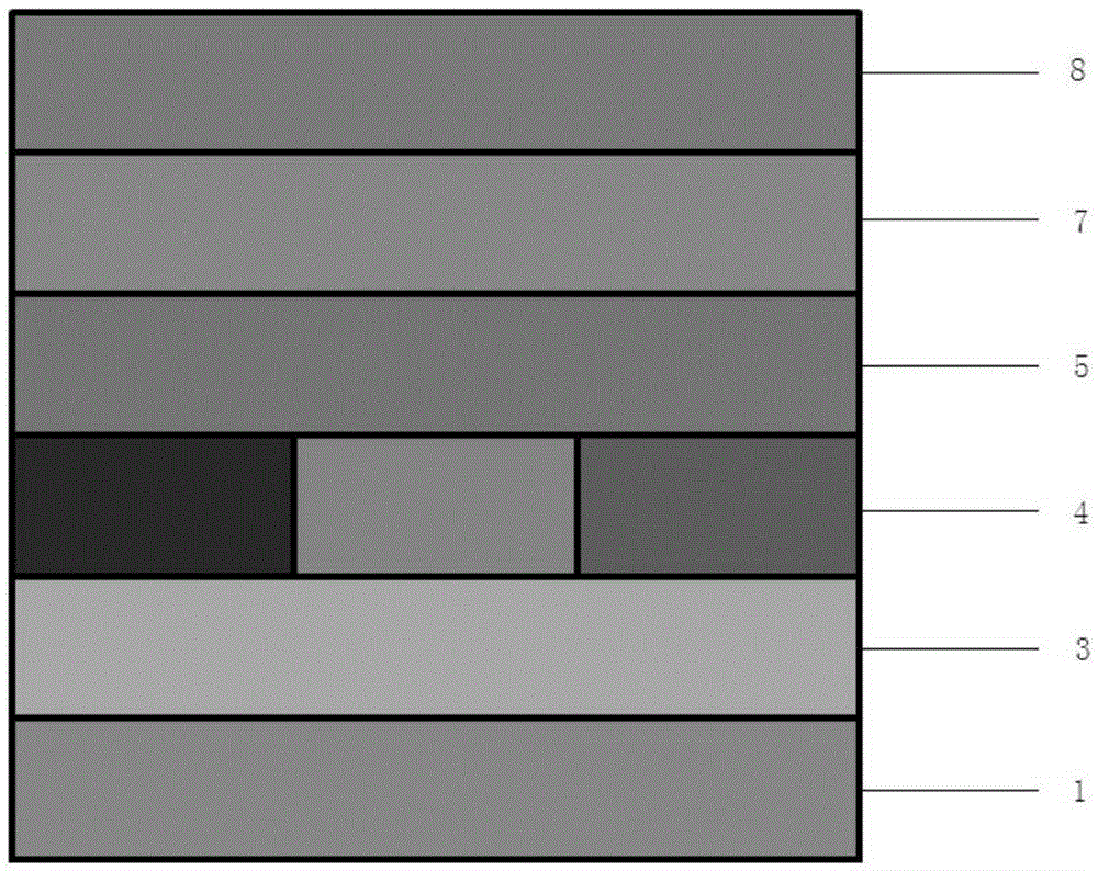
[0049] A QLED comprising a cathode 1, an electron transport layer 3, a quantum dot light-emitting layer 4, a hole transport layer 5, a hole injection layer 7 and an anode 8 which are stacked in sequence, such as figure 1 As shown, the hole transport layer 5 is made of a deep blue light host material. Wherein, the electron transport layer 3 is selected from ZnO nanoparticle film with a thickness of 20-200nm; the hole transport layer 5 is selected from UGH-2 with a thickness of about 5-40nm; the hole injection layer 7 is selected from MoO 3 , with a thickness of 2-20nm; the anode 8 is an Ag or Au high work function metal anode.
[0050] Molecular structural formula of UGH-2:
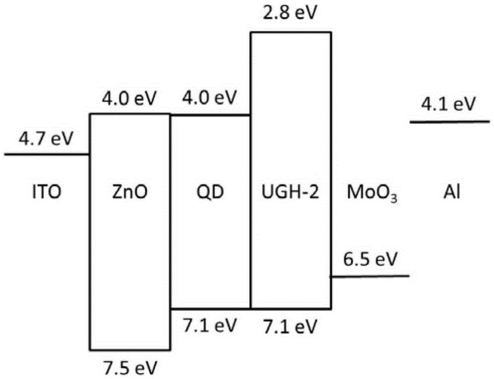
[0051] The molecular structural formula of the UGH-2 is as shown above. On the one hand, the LUMO energy level of the UGH-2 is about 2.8eV, and the HOMO energy level is about 7.1eV, so the hole transport layer 5 and the quantum energy can be effectively reduced. The hole injection barrier between the d...
Embodiment 2
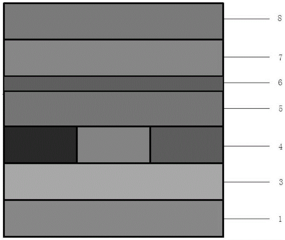
[0057] A QLED comprising a cathode 1, an electron transport layer 3, a quantum dot luminescent layer 4, a hole transport layer 5, a hole transport / injection mixed layer 6, a hole injection layer 7 and an anode 8 stacked in sequence, such as figure 2 As shown, wherein, the hole transport layer 5 is made of deep blue light host material.
[0058] Wherein, the electron transport layer 3 is a ZnO nanoparticle film with a thickness of 20-200nm; the hole transport layer 5 is UGH-2 with a thickness of about 5-40nm; the hole transport / injection mixed layer 6 is UGH -2 with MoO 3 The blend material, wherein, the mass ratio of the UGH-2 to the MoO3 is (100:1)-(100:20), and the thickness of the hole transport / injection mixed layer 6 is 5-10nm; the The hole injection layer 7 is selected from MoO 3 , with a thickness of 2-20nm; the anode 8 is an Ag or Au high work function metal anode. Wherein, the electron transport layer 3 is selected from ZnO nanoparticle film with a thickness of 20...
PUM
| Property | Measurement | Unit |
|---|---|---|
| Thickness | aaaaa | aaaaa |
| Thickness | aaaaa | aaaaa |
| Thickness | aaaaa | aaaaa |
Abstract
Description
Claims
Application Information
 - R&D
- Intellectual Property
- Life Sciences
- Materials
- Tech Scout
- Unparalleled Data Quality
- Higher Quality Content
- 60% Fewer Hallucinations
Browse by: Latest US Patents, China's latest patents, Technical Efficacy Thesaurus, Application Domain, Technology Topic, Popular Technical Reports.
© 2025 PatSnap. All rights reserved.Legal|Privacy policy|Modern Slavery Act Transparency Statement|Sitemap|About US| Contact US: help@patsnap.com