Heat storage device based on heat utilization of waste hot smoke

A heat storage device and hot flue gas technology, applied in the direction of heat storage equipment, heat exchanger types, indirect heat exchangers, etc., can solve the problem that heat can only be discharged into the atmosphere, heat storage devices are less reported, and heat utilization Low efficiency and other problems, to overcome time limitations, improve service life, and save energy

Active Publication Date: 2016-02-03
南京佰盛玻璃技术有限公司
View PDF13 Cites 3 Cited by
  • Summary
  • Abstract
  • Description
  • Claims
  • Application Information

AI Technical Summary

Problems solved by technology

Although there are many heat storage devices currently studied, most of them use hot water or heat transfer oil liquid phase as the heat exchange medium, and there are few reports on heat storage devices that study the utilization of waste heat and flue gas in industrial applications.
[0006] At present, in many factories, such as cement plants, smelting plants, ceramic factories, etc., the recovery of waste heat and flue gas is mainly for drying materials. A large amount of heat can only be discharged into the atmosphere, resulting in a large amount of waste of heat energy, and the efficiency of heat utilization is extremely low

Method used


Image

  • Heat storage device based on heat utilization of waste hot smoke
  • Heat storage device based on heat utilization of waste hot smoke
  • Heat storage device based on heat utilization of waste hot smoke

Examples


Embodiment 1

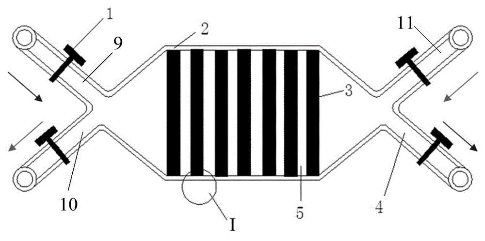
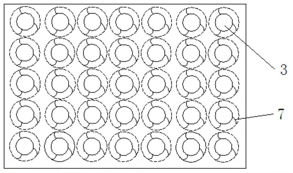
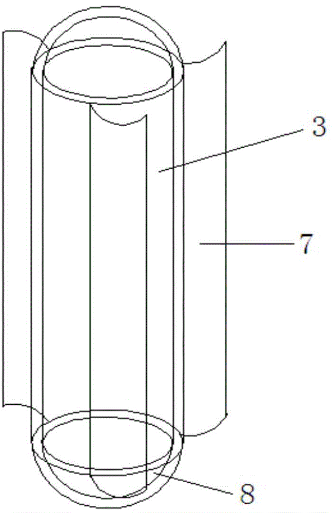
[0033] Such as Figure 1 to Figure 4 As shown, it is a heat storage device based on the heat utilization of waste heat flue gas provided in this embodiment, which includes a heat storage chamber 2, a plurality of heat storage prefabricated parts 3 housed in the heat storage chamber Air intake channel 9, waste heat flue gas exhaust channel 4, cold air intake channel 11 and cold air exhaust channel 10. The waste heat flue gas intake passage 9 and the cold air exhaust passage 10 are connected to one side of the heat storage chamber 2 respectively, and the waste heat flue gas exhaust passage 4 and the cold air intake passage 11 are connected to the other side of the heat storage chamber 2 respectively. connected on one side. A plurality of thermal storage preforms 3 are arranged at intervals, and each thermal storage preform 3 can rotate on its own axis. The gas entering the thermal storage cavity 2 can flow between adjacent thermal storage preforms. The outer wall of the heat ...

Embodiment 2

[0047] This example is roughly the same as Example 1, except that the composition of the heat storage material is: MgCl with a mass fraction of 38.5% 2 , the mass fraction is 61.5% NaCl, the graphene doping amount is MgCl 2 and 1.0% of the total mass of NaCl. Then weigh the heat storage material, mix and grind it until the fineness is about 200 mesh.

[0048] Heat storage performance test:

[0049] The mixed and ground thermal storage material was tested, and the thermal conductivity of the material was 4.2W / (m.k), and the heat of solution was 347kJ / kg. Carry out the heat exchange test on the assembled heat storage device, close the cold air inlet and outlet pipeline valves, and open the waste heat flue gas inlet and outlet pipeline valves. Using hot air at 450°C, the flow rate of the imported waste heat flue gas is 3-5m / s, and the heat exchange is carried out for 1h. Then close the waste heat flue gas inlet and outlet pipe valves, open the cold air intake and exhaust pipe...

Embodiment 3

[0051] This example is roughly the same as Example 1, except that the composition of the heat storage material is: MgCl with a mass fraction of 38.5% 2 , the mass fraction is 61.5% NaCl, the graphene doping amount is MgCl 2 and 1.5% of the total mass of NaCl. Then weigh the heat storage material, mix and grind it until the fineness is about 200 mesh.

[0052] Heat storage performance test:

[0053] The mixed and ground thermal storage material was tested, and the thermal conductivity of the material was 4.6W / (m.k), and the heat of solution was 382kJ / kg. Carry out the heat exchange test on the assembled heat storage device, close the cold air inlet and outlet pipeline valves, and open the waste heat flue gas inlet and outlet pipeline valves. Using hot air at 450°C, the flow rate of the imported waste heat flue gas is 3-5m / s, and the heat exchange is carried out for 1h. Then close the waste heat flue gas inlet and outlet pipe valves, open the cold air intake and exhaust pipe...


PUM


Abstract

The invention provides a heat storage device based on heat utilization of waste hot smoke. The heat storage device comprises a heat storage cavity, a plurality of heat storage preformed parts accommodated in the heat storage cavity, a waste hot smoke inlet channel, a waste hot smoke discharge channel, a cold air inlet channel and a cold air discharge channel. Both the waste hot smoke inlet channel and the cold air discharge channel are communicated with one side of the heat storage cavity. Both the waste hot smoke discharge channel and the cold air inlet channel are communicated with the other side of the heat storage cavity. The multiple heat storage preformed parts are arranged at intervals, and each heat storage preformed part can rotate around the axis of the heat storage preformed part. According to the heat storage device based on heat utilization of the waste hot smoke, the waste hot smoke can be utilized effectively, so that the energy utilization efficiency is improved; at the same time, the preformed parts and an assembling technology are adopted, industrial production can be conducted by a large margin, and the production efficiency is improved; a little of grapheme is mixed, so that the heat exchange efficiency of the heat storage device can be improved, and large application value is achieved.

Description

technical field [0001] The invention relates to a heat storage material, in particular to a heat storage device based on heat utilization of waste heat flue gas. Background technique [0002] Energy is the material basis for the survival and development of human society. At present, the energy consumed in my country mainly comes from non-renewable mineral energy such as coal, oil, and natural gas. With the further development of our country's society and economy, the demand for energy continues to grow. Building a stable, economical, clean and secure energy supply system is facing major challenges. A large number of high-energy-consuming enterprises such as iron and steel plants, cement plants, and power plants in my country consume a large amount of energy every year and generate a large amount of waste heat. Due to current technical limitations, a large amount of heat energy is not fully utilized and is directly discharged into the atmosphere, resulting in energy waste. ....

Claims


Application Information

Patent Timeline
Patent Type & Authority Applications(China)
IPC IPC(8): F28D20/00
CPCY02E60/14
Inventor 周卫兵朱教群李儒光程晓敏李元元原郭丰唐文学
Owner 南京佰盛玻璃技术有限公司
Why Eureka
Try Eureka