A thermal interface material for chip detection and its preparation method

A thermal interface material and chip detection technology, applied in the direction of heat exchange materials, chemical instruments and methods, etc., can solve the problems of thermal conductivity of contaminated chips, insufficient buffer of thermal interface materials, etc., achieve low pollution characteristics, reduce pollution phenomena, and withstand Good wear performance

Inactive Publication Date: 2019-01-22
HUAZHONG UNIV OF SCI & TECH
View PDF6 Cites 0 Cited by
  • Summary
  • Abstract
  • Description
  • Claims
  • Application Information

AI Technical Summary

Problems solved by technology

[0004] Aiming at the above defects or improvement needs of the prior art, the present invention provides a thermal interface material for chip detection, aiming to solve the problems of insufficient buffering of conventional thermal interface materials, contamination of the chip and low thermal conductivity during the chip detection process

Method used


Image

  • A thermal interface material for chip detection and its preparation method
  • A thermal interface material for chip detection and its preparation method
  • A thermal interface material for chip detection and its preparation method

Examples


preparation example Construction

[0030] The present invention also provides a preparation method of the above-mentioned thermal interface material, comprising the following steps:

[0031] (1) Mix the high thermal conductivity filler with the polymer carrier at a ratio of 1:1 to 8:1, and disperse evenly in an organic solvent (such as ethyl acetate, butyl acetate, acetone, toluene, xylene or ethanol, etc.) , to obtain a thermally conductive coating; in the preparation process, a pressure-sensitive adhesive with a mass of 0.5% to 10% of the total mass of the solid can also be added; the volume of the organic solvent is mainly limited by the solubility of the polymer carrier and the pressure-sensitive adhesive. Silicone oil is used as a polymer carrier. When silicone pressure-sensitive adhesive is used, the polymer carrier and pressure-sensitive adhesive can be dissolved by adding an organic solvent of about the same quality;

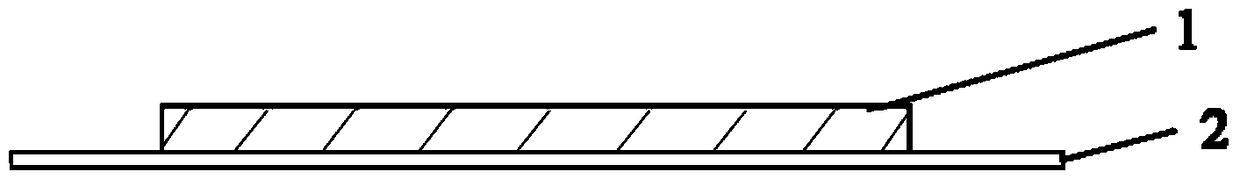
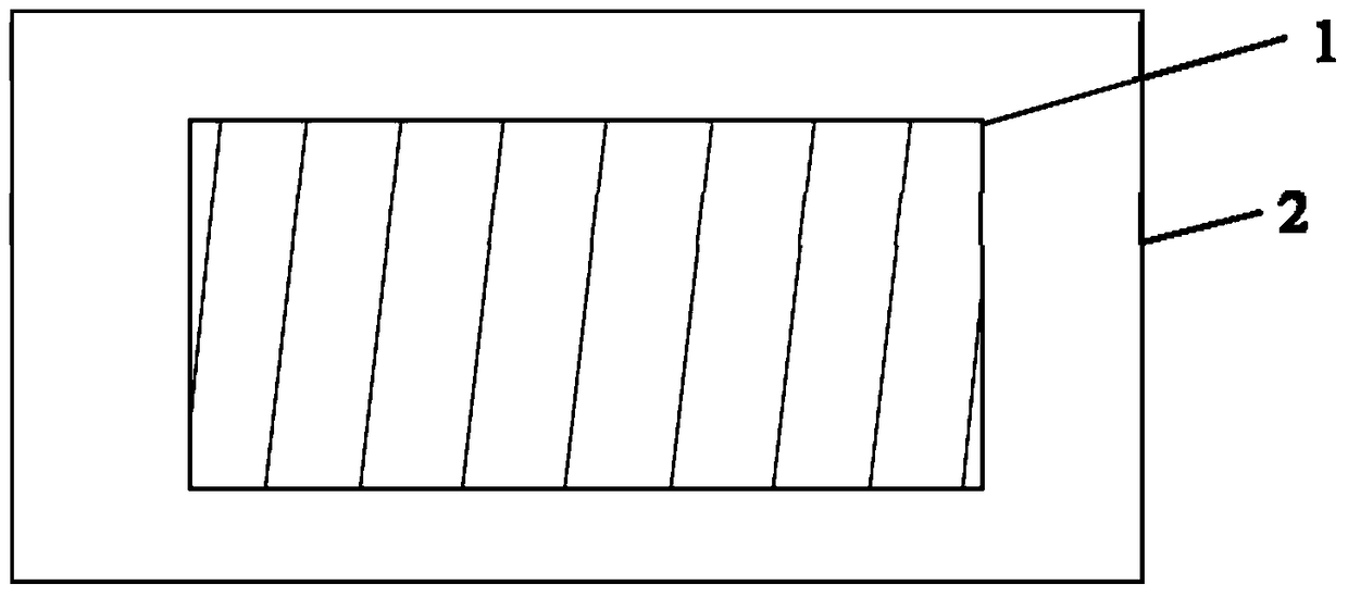
[0032] (2) Coating the thermally conductive paint obtained in the step (1) on all or ...

Embodiment 1

[0036] (1) First take 0.7g of hydroxyl silicone oil and 0.3g of silicone pressure-sensitive adhesive, dissolve them in 1g of toluene, add 4.0g of copper powder with a particle size of less than 50μm, and stir and mix them evenly;

[0037] (2) Apply the above mixture evenly on the surface of copper foil with a thickness of 35 μm;

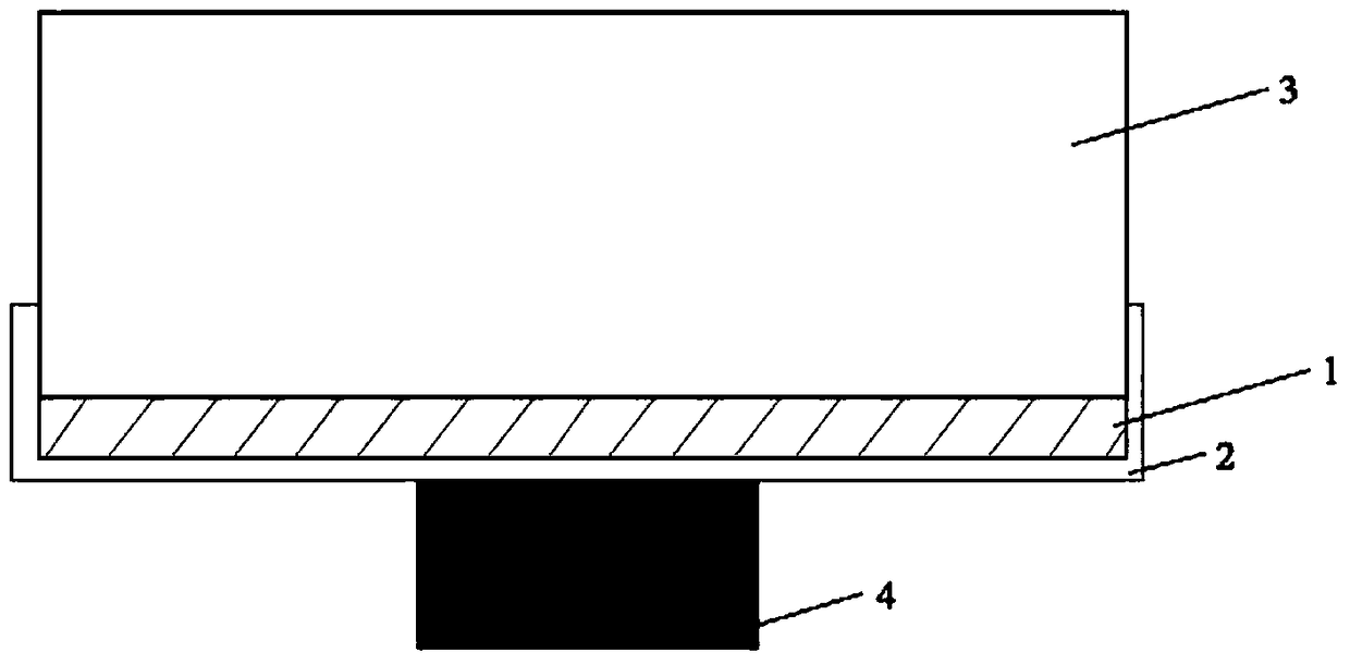
[0038] (3) Heating at 80° C. for 30 minutes to completely volatilize the solvent, and prepare the thermal interface material. The surface coating thickness of the thermal interface material is about 300 μm.

[0039] Tested with a thermal conductivity testing device, the measured thermal conductivity of the material is 4.49W / (m·K).

Embodiment 2

[0041] Repeat Example 1 with the same steps as described, the difference is that the copper powder is replaced by a 4:1 mixture of copper powder with a particle size of less than 50 μm and silver powder with a particle size of less than 50 nm, and the thermal conductivity of the material measured at last is 6.24W / (m·K).


PUM

PropertyMeasurementUnit
thicknessaaaaaaaaaa
sizeaaaaaaaaaa
thicknessaaaaaaaaaa

Abstract

The invention discloses a thermal interface material for chip testing. The thermal interface material comprises a coating which is 300-600 [mu]m thick and a piece of metal foil which is 20-200 [mu]m thick, wherein the whole or partial surface of the metal foil is covered with the coating; the coating comprises a high-thermal-conductivity filler and a high-molecular carrier; the mass ratio of the high-thermal-conductivity filler to the high-molecular carrier is (1-8):1; the heat conductivity coefficient of the thermal interface material is 4-10 W / (m.K). The invention further discloses a preparation method of the thermal interface material and application to the chip testing. The thermal interface material is high in thermal conductivity and buffer performance, and used for transferring heat of a testing pressure head to the surface of a tested chip in the testing process, so as to guarantee a stable testing temperature environment for the chip testing. The thermal interface material can be widely applied to testing of the thermal stability of electronic components and chips.

Description

technical field [0001] The invention belongs to the field of thermal interface materials, and more specifically relates to a thermal interface material used for chip detection and a preparation method thereof. Background technique [0002] With the development of electronic components towards miniaturization and multi-function, the integration and assembly density of electronic products continue to increase, and the thermal stability of chips has become a key bottleneck restricting the development of electronic technology. The work efficiency and reliability of electronic products are getting higher and higher. More and more rely on the solution of chip thermal stability problem. In the industrial production of integrated circuits, after the chip is manufactured, it is necessary to use the process platform detection system to verify whether the chip can work normally at a specific temperature, that is, to detect the reliability of the chip. The test indenter of the test sys...

Claims


Application Information

Patent Timeline
Patent Type & Authority Patents(China)
IPC IPC(8): C09K5/14
Inventor 吴丰顺蔡雄辉王沈柳入华杨维平
Owner HUAZHONG UNIV OF SCI & TECH
Why Eureka
Try Eureka