Weaving method of woven spacer fabric structural antenna

A technology of weaving spacer fabrics and spacer fabrics, which is applied in the directions of antenna grounding devices, radiating element structures, antenna supports/mounting devices, etc., which can solve problems such as collapse, delamination, and antenna system failure, and achieve light weight and high gain Good performance, the effect of improving mechanical properties

Inactive Publication Date: 2016-02-10
DONGHUA UNIV
View PDF2 Cites 8 Cited by
  • Summary
  • Abstract
  • Description
  • Claims
  • Application Information

AI Technical Summary

Problems solved by technology

Although this structure is a big step forward than the previous structure, the antenna system is prone to serious damage such as delamination and collapse when it is subjected to impact loads, resulting in the failure of the antenna system

Method used


Image

  • Weaving method of woven spacer fabric structural antenna
  • Weaving method of woven spacer fabric structural antenna
  • Weaving method of woven spacer fabric structural antenna

Examples


Embodiment 1

[0042] Embodiment 1: E-glass fiber spacer composite material microstrip antenna

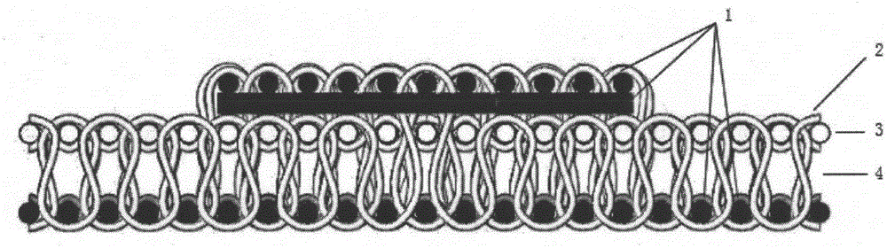
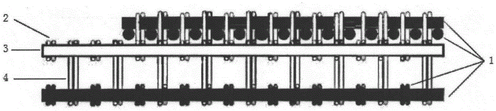
[0043] (1) E glass fiber provided by Zhejiang Jushi Group is selected as the fiber composite reinforcement. The warp yarn 3 fineness of the glass fiber is 1102tex, the weft yarn 2 fineness is 600tex, and the spacer yarn 4 fineness is 370tex. The conductive yarn 1 used in this example is a copper stranded wire provided by Wuxi Liz Precision Electrical Wire Co., Ltd., wherein the diameter of the warp yarn 3 is 0.3 mm, and the diameter of the weft yarn 2 is 0.5 mm. JL-235 type resin and JH-242 type curing agent provided by Changshu Jiahua Co., Ltd. are selected. The resin and curing agent are uniformly mixed according to the ratio of 3:1 during molding, and the curing temperature is 50°C-70°C.

[0044] (2) The working frequency of the antenna designed in this embodiment is 1.5 GHz, the thickness of the prepared spacer glass fiber composite material is 5 mm, and its dielectric constant εr=2.5, which ...

Embodiment 2

[0047] Example 2: Microstrip antenna made of low-dielectric glass fiber spacer composite material

[0048] (1) The low dielectric loss performance fiber selected in this embodiment is E glass fiber, and its fineness is 300tex. The conductive yarn 1, resin and curing agent selected are the same as those in Embodiment 1.

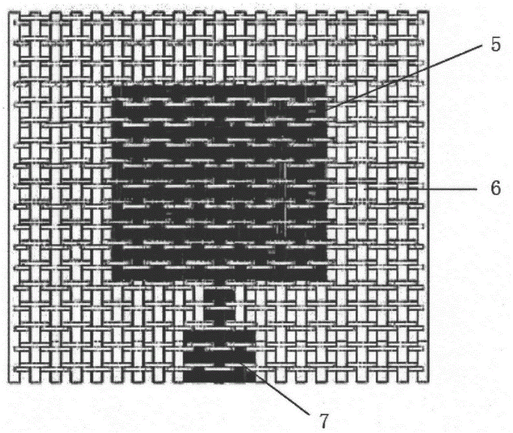
[0049] (2) The operating frequency of the antenna designed in this embodiment is 1.5 GHz, and the thickness of the prepared spacer glass fiber composite material is 2 mm, and its dielectric constant εr=2, which can be calculated according to empirical formulas 1-1 to 1-8 to obtain a single Dimension parameters of radiating element 5 microstrip antenna, such as Figure 4shown. Where W and L are the width and length of the radiating element 5 respectively, WG and LG are the width and length of the finished conformal carrying microstrip antenna, FL is the length of the microstrip line 7 , and FD is the width of the microstrip line 7 .

[0050] (3) Weaving a mic...

Embodiment 3

[0053] Embodiment 3: Microstrip antenna with single radiating element 5 based on aramid spacer fabric

[0054] (1) Aramid fiber is selected as the fiber composite reinforcement with a fineness of 167tex; nylon silver-plated yarn is selected as the conductive yarn 1 with a fineness of 20tex.

[0055] (2) The operating frequency of the single radiating element 5 microstrip antenna designed in this embodiment is 2.4GHz, and the density and thickness of the spaced aramid fiber composite material are the same as in Embodiment 1, and its dielectric constant εr=1.8, according to experience Formulas 1-1 to 1-8 can be used to calculate the size parameters of the single radiating element 5 microstrip antenna, such as Figure 4 shown. Where W and L are the width and length of the radiating element 5 respectively, WG and LG are the width and length of the finished conformal carrying microstrip antenna, FL is the length of the microstrip line 7 , and FD is the width of the microstrip line...


PUM


Abstract

The invention discloses a weaving method of a woven spacer fabric structural antenna. The method comprises the following steps: selecting conductive yarns, weaving the conductive yarns and fibers with low-dielectric-loss performance into a radiation element and a grounding plate of the spacer fabric microstrip antenna, wherein the radiation element and the grounding plate are respectively used as a top layer and a bottom layer of the spacer fabric; and compositing a microstrip antenna preformed part with a coaxial feed and an appropriate resin material to obtain the spacer composite material microstrip antenna structure. Since the woven spacer fabric has a hollow structure characteristic, the microstrip antenna is light in weight, resistant to impact, unlikely to layer, capable of greatly improving the reliability and prolonging the service life of the antenna and wide in application prospect in the fields such as aerospace, transportation and information.

Description

technical field [0001] The invention relates to a microstrip antenna capable of bearing external forces and receiving transmitted signals, in particular a microstrip antenna system designed based on woven spacer fabrics. Background technique [0002] Antennas are an essential component of communication systems and are widely used in civil and military fields. As an essential communication device, a large number of antennas are installed on the aircraft. The early antennas are protruding structures, which are easy to be damaged and affect the aerodynamic performance of the aircraft. Therefore, the traditional protruding antennas are not used in the modern aerospace field, but the antennas with a planar structure lying flat on the surface of the fuselage. However, this kind of antenna is still not a part of the fuselage and cannot play the role of bearing stress. At the same time, in low-frequency band communication, the size of the antenna will increase with the increase of...

Claims


Application Information

Patent Timeline
Patent Type & Authority Applications(China)
IPC IPC(8): H01Q1/22H01Q1/38H01Q1/48H01Q1/50
Inventor 许福军王义斌谢惺邱夷平
Owner DONGHUA UNIV
Why Eureka
Try Eureka