Current-controlled permanent magnet speed controller

A technology of permanent magnet governor and current control, which is applied in electric brakes/clutches, permanent magnet clutches/brakes, and connected to control/drive circuits, etc., which can solve the problem of large eddy current power consumption, poor torque transmission capability, and waste of rare earth Resources and other issues, to achieve the effect of reducing electric heat loss, improving torque transmission capacity, and saving rare earth materials

Inactive Publication Date: 2016-02-10
刁俊起
View PDF5 Cites 4 Cited by
  • Summary
  • Abstract
  • Description
  • Claims
  • Application Information

AI Technical Summary

Problems solved by technology

At present, the commonly used permanent magnet governors realize the power transmission by cutting the conductors with permanent magnets to generate eddy currents. The speed adjustment is realized by adjusting the air gap or the magnetic force of the permanent magnets. Due to the constraints of the conductor characteristics, the eddy current power consumption is large, and there are Disadvantages such as poor torque transmission capability, high assembly difficulty, waste of a lot of rare earth resources, etc.

Method used


Image

  • Current-controlled permanent magnet speed controller
  • Current-controlled permanent magnet speed controller
  • Current-controlled permanent magnet speed controller

Examples


Embodiment 1

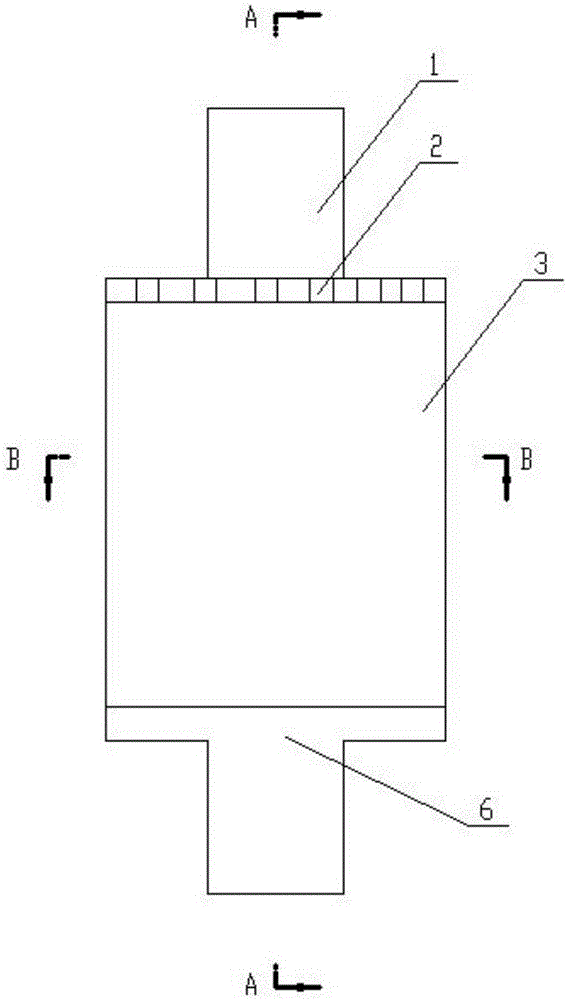
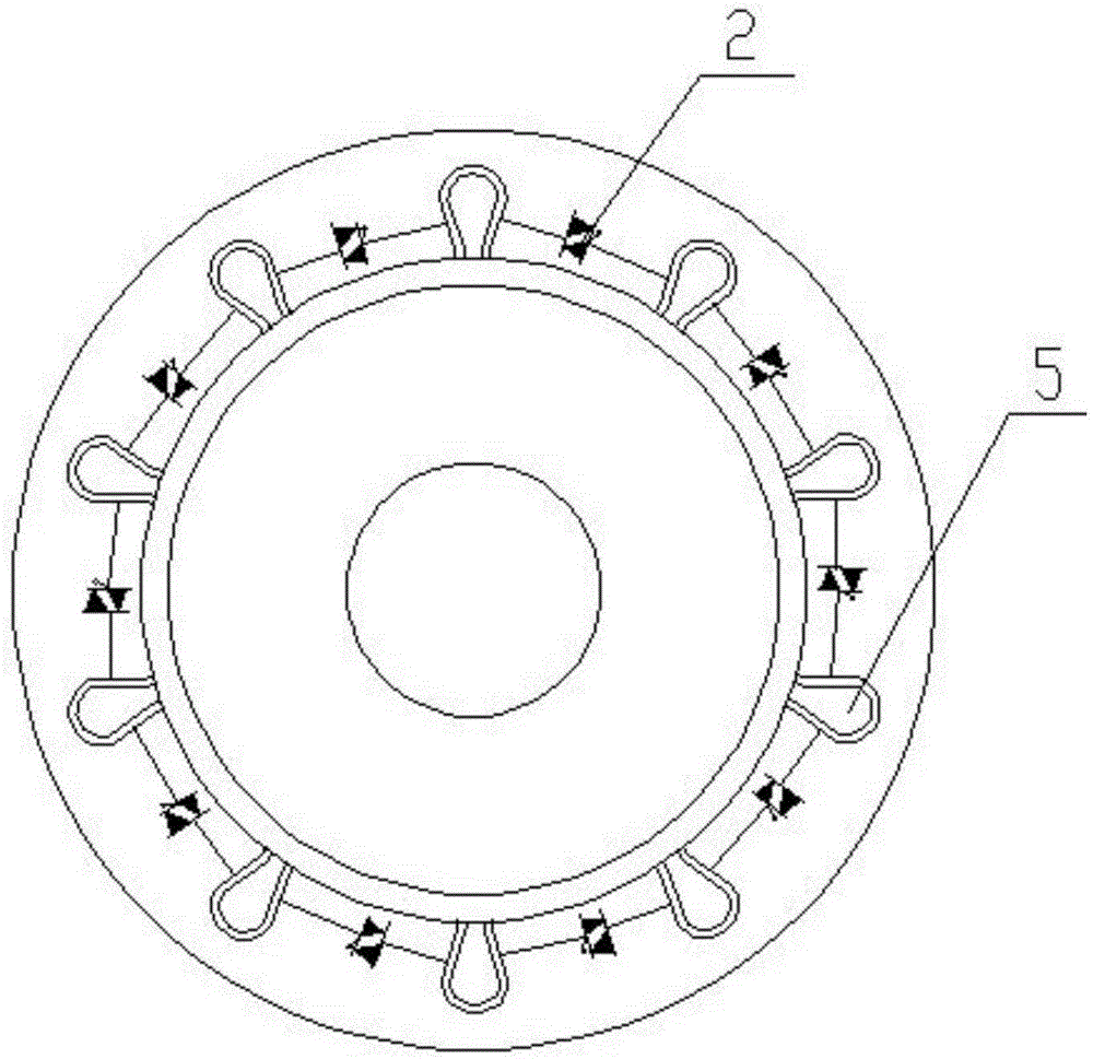
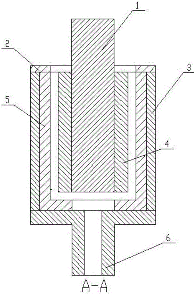
[0017] A current-controlled permanent magnet governor, comprising a squirrel-cage conductor rotor 3 connected to a drive shaft 6 and a permanent magnet rotor 4 connected to a driven shaft 1, the inner surface of the squirrel-cage conductor rotor 3 is inlaid with a squirrel cage The conductor 5, the ends of all the squirrel-cage conductors 5 are connected by setting end rings and form a squirrel-cage structure; every two adjacent squirrel-cage conductors are connected with thyristors 2 .

[0018] Such as Figure 5 As shown, the circuit for controlling the on-off of the thyristor is as follows: the potentiometer RB, the potentiometers R1 to R2n and the capacitor C1 form a phase-shift trigger network, and the potentiometer R2n-1 and the potentiometer R2n each take one end and connect to the two ends of the thyristor VTn respectively; The other end of the potentiometer R2n-1 is connected to one end of the capacitor C1, and the other end of the capacitor C1 is connected to the othe...

Embodiment 2

[0020] Such as Figure 6 As shown, the circuit for controlling the on-off of the thyristor includes a pulse generator composed of 555 and potentiometers R1 to R2n, thyristors VT1 to VTn connected to the potentiometer R2n-1 and one end of the potentiometer R2n, and the potentiometer R2n-1 is another One end is connected to the signal output end of the pulse generator, and the ground end of the pulse generator is connected to the other end of the potentiometer R2n.

[0021] The pulse generator composed of 555 provides bidirectional photoelectrically isolated pulses. The trigger power of the triac VT1 to VTn comes from the coil itself, which is isolated from the external circuit. The isolated pulse triggers the conduction of the bidirectional thyristor VT1 to VTn. All the other parts are the same as in Example 1.


PUM


Abstract

The invention relates to a current-controlled permanent magnet speed controller. The current-controlled permanent magnet speed controller comprises a mouse cage conductor rotor connected with a driving shaft and a permanent magnet rotor connected with a driven shaft, wherein the mouse cage conductor is inlaid in the inner surface of the mouse cage conductor rotor, the end parts of mouse cage conductors are connected by arranging end rings, so as to form a mouse cage structure; and a thyristor which can be controlled to be on or off is connected between every two adjacent mouse cage conductors. The current-controlled permanent magnet speed controller adopts a fixed magnetic gap structure, so that meshing area of the speed controller is greatly increased, assembling difficulty is reduced, size is reduced, rare earth material is saved, and torque transmitting capacity is greatly improved; electric heating loss is reduced by enlarging the cross sections of the mouse cage conductors and reducing resistances of the conductors; and a magnetic gap or magnetic force regulating mechanism is eliminated, so that a control mechanism is greatly simplified, the size is reduced, the aims of saving energy and reducing consumption are realized to the utmost extent, material and electric energy consumption is reduced, mounting space is also saved, and convenience is provided for field mounting construction.

Description

technical field [0001] The invention relates to a permanent magnet governor, in particular to a current-controlled permanent magnet governor. Background technique [0002] The permanent magnet speed governor uses the magnetic coupling speed of the permanent magnet to realize the soft (magnetic) connection between the motor and the load, without any harmonic generation affecting the power grid, and has high reliability. , Inflammable and explosive, voltage instability and lightning and other harsh environments, greatly reducing mechanical vibration, widely used in electric power, steel, metallurgy, petrochemical, papermaking, municipal, ships, irrigation and mining industries. At present, the commonly used permanent magnet governors realize the power transmission by cutting the conductors with permanent magnets to generate eddy currents. The speed adjustment is realized by adjusting the air gap or the magnetic force of the permanent magnets. Due to the constraints of the cond...

Claims


Application Information

Patent Timeline
Patent Type & Authority Applications(China)
IPC IPC(8): H02K49/10H02K11/33
CPCH02K49/106
Inventor 刁俊起王忠亮张磊李强王秀张学凯
Owner 刁俊起
Why Eureka
Try Eureka