Distributed surface acoustic wave resonator and surface acoustic wave sensing system

A surface acoustic wave and distributed technology, which is applied in the direction of instruments, scientific instruments, and record carriers used by machines, can solve the problems of large surface acoustic wave sensors and other problems, and achieve a small footprint, easy implementation, and simple circuit structure. Effect

Active Publication Date: 2016-02-10
MESNAC
View PDF4 Cites 2 Cited by
  • Summary
  • Abstract
  • Description
  • Claims
  • Application Information

AI Technical Summary

Problems solved by technology

[0006] In order to solve the technical problem that the existing surface acoustic wave sensor occupies a large volume, the present invention provides a surface acoustic wave resonator type vibration sensor

Method used


Image

  • Distributed surface acoustic wave resonator and surface acoustic wave sensing system
  • Distributed surface acoustic wave resonator and surface acoustic wave sensing system
  • Distributed surface acoustic wave resonator and surface acoustic wave sensing system

Examples


Embodiment 1

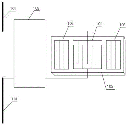
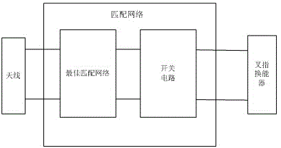
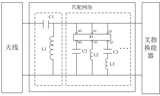
[0027] Embodiment one, see figure 1 As shown, this embodiment provides a distributed surface acoustic wave resonator, including an antenna 101, a matching network 102, a reflection grid 103, and an interdigital transducer 104, at least the reflection grid 103, and the interdigital transducer 104 Set on the piezoelectric substrate 105, see figure 2 As shown, the matching network 102 includes an optimal matching network composed of at least one capacitor and at least one inductor, and the optimal matching network is also connected in parallel with a switch circuit, and the switch circuit includes several branches connected in parallel, each branch At least one capacitance and / or inductance device is provided, and a switch for controlling the conduction state of the branch is also provided on each branch of the switch circuit. The working principle of the distributed surface acoustic wave resonator in this embodiment is: the antenna 101 receives the excitation signal. In this e...

Embodiment 2

[0028] Embodiment 2, this embodiment provides a preferred circuit of a distributed surface acoustic wave resonator, wherein the switch circuit uses on-site programming to control the switch circuit, see image 3 As shown, the switches of each branch of the switch circuit are controlled by the field programming control logic device P1.

[0029] As a preferred embodiment, the field programming control logic device P1 includes n groups of external contacts. In this embodiment image 3 3 sets of external contact points are given in , namely (M1, M2), (N1, N2), (Q1, Q2), and these 3 sets of contacts are respectively connected to the 3 branches of the switch circuit, namely , each branch of the switch circuit has a group of external contacts in series, and the on-site programming control logic device P1 controls the conduction state of each group of external contact points through programming. For example, when the on-site programming control logic device P1 controls (M1, M2 ) is t...

Embodiment 3

[0034] Embodiment 3. This embodiment illustrates the basic principle of the distributed surface acoustic wave resonator in Embodiment 2. Since capacitors and / or inductors are connected in series in each branch, no matter whether any branch is newly connected to the matching network, Both will change the reactance value of the matching network. This embodiment gives another way of incorporation, see Figure 4 As shown, the equivalent capacitive reactance of the matching network is C′, the equivalent inductive reactance L′, and the calculation method of the impedance value Zeq2 of the matching network is:

[0035] (1)

[0036] (2)

[0037] The general near-resonator equivalent circuit model of a resonator is as Figure 5 as shown, Figure 5 C and L are the dynamic capacitance and inductance caused by the elasticity and inertia of the piezoelectric substrate, respectively, R is the dynamic resistance caused by damping, C0 is the static capacitance of the IDT, and R0 is th...


PUM


Abstract

The invention discloses a distributed surface acoustic wave resonator and a surface acoustic wave sensing system. The distributed surface acoustic wave resonator comprises a first antenna, a matching network, a reflecting grating and an interdigital transducer, wherein at least the reflecting grating and the interdigital transducer are arranged on a piezoelectric substrate; the matching network comprises an optimal matching network composed of at least one capacitor and at least one inductor, and the optimal matching network is further connected with a switch circuit in parallel; the switch circuit comprises a plurality of branches connected in parallel, each branch is provided with at least one capacitor and / or inductor device, and each branch of the switch circuit is further provided with a switch for controlling on-off state of the branch. According to the distributed surface acoustic wave resonator provided by the invention, when the matching network is connected with different branch, correspondingly, the resonator is corresponding to one center frequency, and the center frequency of the resonator can be changed just by changing the connected branch under control; and the distributed surface acoustic wave resonator has simple structure, and occupies small space.

Description

technical field [0001] The invention relates to a surface acoustic wave sensor, in particular to a distributed surface acoustic wave resonator. Background technique [0002] Radio Frequency Identification (RFID, Radio Frequency Identification) technology is a technology that applies non-contact tags, which automatically identify target objects and obtain relevant data through radio frequency signals. The single-port surface acoustic wave (SAW) resonator is an important part of the radio frequency identification product, including the interdigital transducer (IDT) and the reflective grid. The reflective grid is used to form an acoustic resonant cavity, and the interdigital transducer Transducers are used for the mutual conversion between sound and electricity. [0003] The surface acoustic wave excited by the IDT on the surface of the substrate is reflected back and forth between the reflection gratings. When the external signal excitation frequency f is equal to the center ...

Claims


Application Information

Patent Timeline
Patent Type & Authority Applications(China)
IPC IPC(8): H03H9/25
CPCG01K11/265G06K19/0675G06K19/0726H03H7/38H03H9/642H03H2007/386
Inventor 董兰飞滕学志陈海军韦江波佟强
Owner MESNAC
Why Eureka
Try Eureka