
High-power seeker tile type active phased array antenna

A phased array antenna, high-power technology, applied in the field of electronics, can solve the problems of long thermal path, indeterminate, affecting the chip amplitude and phase consistency, etc., to achieve the effect of improving reliability, shortening thermal path, and reducing volume

Active Publication Date: 2016-02-24
10TH RES INST OF CETC
View PDF12 Cites 59 Cited by
  • Summary
  • Abstract
  • Description
  • Claims
  • Application Information

AI Technical Summary

Problems solved by technology

[0009] To sum up, the current domestic and foreign literature reports mainly adopt the brick-type modular design of the seeker active phased array antenna, which mainly transfers the heat from the TR component to the array surface and then transfers the heat to the outside of the array. Exchange with the heat exchanger, the disadvantage of the heat dissipation method is: the reliability of the active phased array antenna is poor, because the heat path of the active phased array antenna is long, and the heat of the high-power chip cannot be directly introduced into the heat exchanger quickly, causing the high-power chip to be easily damaged. Burned out; secondly, the excessively long thermal path leads to a large temperature difference of the high-power chip of each channel, which affects the consistency of the chip's amplitude and phase, resulting in the need for temperature compensation of the active phased array antenna of the seeker
At present, there is no confirmed technical solution for the high-power seeker tile-type active phased array antenna that can directly introduce heat into the heat exchanger and does not require temperature compensation.

Method used


Image

  • High-power seeker tile type active phased array antenna
  • High-power seeker tile type active phased array antenna
  • High-power seeker tile type active phased array antenna

Examples


Embodiment Construction

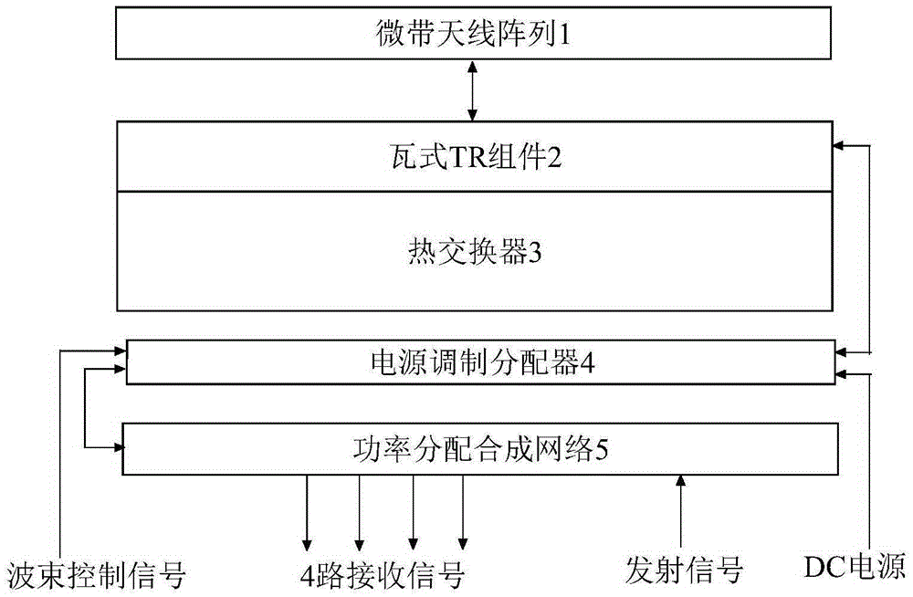
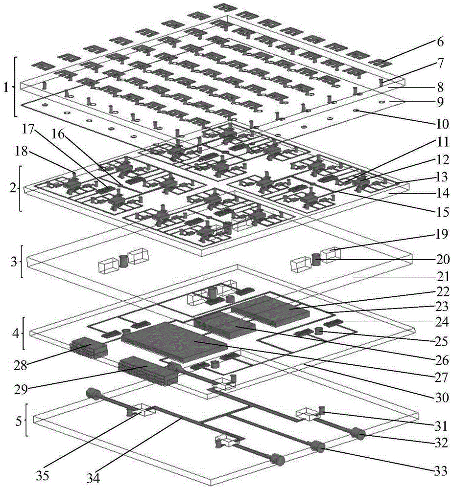
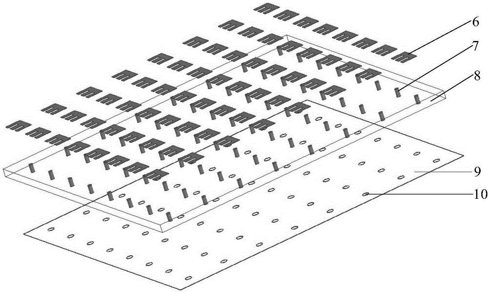
[0028] refer to Figure 1-Figure 2 . In the embodiment described below, a high-power seeker tile-type active phased array antenna includes a microstrip antenna array 1, a tile-type TR assembly 2, a heat exchanger 3, a power modulation distributor 4 and a power distribution The synthetic network 5 is characterized in that: the microstrip antenna array 1 uses an E-type patch 6 as a radiation array element, and the distance between the radiation array elements is set between 0.45 and 0.55 wavelengths of the operating frequency, and is set according to the entire size of the 4×4 array. Multiples are expanded, and a rectangular grid array is used to lay out on the antenna dielectric substrate 8. The tile-type TR assembly 2 is integrated and closely connected to the heat exchanger 3; the feeding probe 7 of the microstrip antenna array 1 passes through the antenna dielectric substrate 8 and the antenna The feeding vias 10 on the base plate 9 are connected to the high-power transceiv...


PUM


Abstract

The invention discloses a high-power seeker tile type active phased array antenna, and aims at providing an active phased array antenna which is small in size and low in weight and can reliably work with no requirement for temperature compensation. The high-power seeker tile type active phased array antenna is realized by the following scheme that E-type patches act as radiation array elements of a microstrip antenna array which can be extended according to integral multiples of 4x4 array scale, rectangular grid arrays are distributed on an antenna dielectric substrate, and a tile type TR component is closely connected with a heat exchanger integrally; and the microstrip antenna array is connected with the high-power transmit-receive chips of the tile type TR component to form transmit-receive channels through integration, every four high-power transmit-receive chips are connected with one TR multifunctional chip simultaneously, four TR multifunctional chips form one 4x4 subarray circuit module together, and then subsequent connection with a power distribution synthesis network is performed. Power supply, high-power pulse power modulation and amplitude-phase code control of a DC power supply and wave beam control signals are realized via a power supply modulation distributor so that directional diagram scanning of the high-power tile type active phased array antenna can be realized.

Description

technical field [0001] The invention relates to a high-power, high-efficiency heat storage, and high-density integrated seeker active phased array antenna in the field of electronic technology. Background technique [0002] In the 1980s, the United States commissioned Martin Marietta to develop a planar phased array antenna for the seeker using brick design technology. The phased array antenna works in the W band (94GHz), and the antenna diameter is 127mm. There are 2208 antennas in total. Array element, the peak power of the array element is 100mW, and the combined power is 62W. In 2002, the U.S. Defense Advanced Research Projects Agency invested in the development of a micro-electromechanical system (MEMS) electronically scanned antenna. The electronically scanned antenna array of the seeker adopts brick design technology and works in the X and Ka bands; the X-band consists of 60 The radio frequency radiation power of each radiation array unit is 500mW, and the total radi...

Claims


Application Information

Patent Timeline
Patent Type & Authority Applications(China)
IPC IPC(8): H01Q1/50H01Q21/00H05K7/20
CPCH01Q1/50H01Q21/00H05K7/2039
Inventor 何庆强何海丹陈军全
Owner 10TH RES INST OF CETC
Learn More