
Laser frequency stabilizing system

A laser and frequency stabilization technology, applied in the field of lasers, can solve the problems of insensitivity to error signals, limiting the locking effect of lasers to be stabilized, and high cost, and achieve the effects of narrowing line width, ensuring long-term stability, and improving short-term stability

Active Publication Date: 2016-03-02
JIANGHAN UNIVERSITY
View PDF5 Cites 4 Cited by
  • Summary
  • Abstract
  • Description
  • Claims
  • Application Information

AI Technical Summary

Problems solved by technology

[0006] First, when the signal output by the photoelectric detector is input into the computer, if the acquisition rate of the data acquisition card is low, the delay of the feedback will be caused by the problem of transmission speed, and if the acquisition rate of the data acquisition card is high, it will cause cost Too high; second, piezoelectric ceramics are always in a scanning state, because the scanning of piezoelectric ceramics is nonlinear, therefore, the same scanning voltage may correspond to different scanning lengths of piezoelectric ceramics, and at the same time, due to the different lengths of piezoelectric ceramics The different voltage sensitivities of the transmission cavity may cause the insensitivity of the error signal, thus limiting the locking effect of the laser to be stabilized; third, the frequency stabilization of the transmission cavity can only control the long-term drift of the laser, and does not contribute to the narrowing of the laser linewidth not big

Method used


Image

  • Laser frequency stabilizing system

Examples


Embodiment Construction

[0024] In order to make the object, technical solution and advantages of the present invention clearer, the implementation manner of the present invention will be further described in detail below in conjunction with the accompanying drawings.

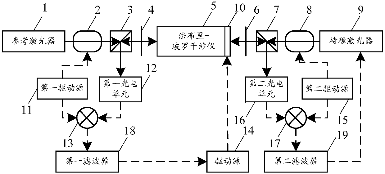
[0025] figure 1 It is a schematic structural diagram of a laser frequency stabilization system provided by an embodiment of the present invention, and the system includes:

[0026] The reference laser 1, the first electro-optic modulator 2, the first polarization beam splitter 3, the first half-wave plate 4, the Fabry-Perot interferometer 5, the second half-wave plate 6, the second The polarization splitter prism 7 , the second electro-optic modulator 8 and the laser to be stabilized 9 , the laser emitting ends of the reference laser 1 and the laser to be stabilized 9 face the Fabry-Perot interferometer 5 .

[0027] The piezoelectric ceramic 10 fixed on the transmission cavity of the Fabry-Perot interferometer 5 is used to generate th...


PUM


Abstract

The invention discloses a laser frequency stabilizing system and belongs to the laser device field. The system comprises a reference laser device, a first electric light modulator, a first polarization splitting prism, a first half-wave plate, a Fabry-Perot interferometer, a second half-wave plate, a second polarization splitting prism, a second electric light modulator and a to-be-stabilized laser device and further comprises a piezoelectric ceramic, a first driving source outputting a first reference signal to the first electric light modulator, a first photoelectric unit arranged on a reflection light path of the first polarization splitting prism, a first frequency mixer mixing a first oscillation signal with a frequency signal outputted by the first photoelectric unit, a driving source generating a voltage signal according to a signal outputted by the first frequency mixer, a second driving source outputting a second reference signal to the second electric light modulator, a second photoelectric unit arranged a reflection light path of the second polarization splitting prism, and a second frequency mixer mixing a second oscillation signal with a frequency signal outputted by the second photoelectric unit.

Description

technical field [0001] The invention relates to the field of lasers, in particular to a laser frequency stabilization system. Background technique [0002] Semiconductor lasers are important laser light sources in scientific research and industry. [0003] The linewidth of semiconductor lasers is about 10MHz, and its long-term drift index is >100MHz / 1h. In the research of laser cooling of atoms, it is usually required that the linewidth of semiconductor lasers is less than 1MHz or even 10kHz, and the drift within a few hours is also within 1MHz. . In order to meet the stability requirements of semiconductor lasers in related research, the following methods are usually used to achieve frequency stabilization of semiconductor lasers: saturation absorption frequency stabilization, Zeeman frequency stabilization, polarization spectrum stabilization, external cavity frequency stabilization and transmission cavity stabilization. frequency. [0004] Among them, the frequency ...

Claims


Application Information

Patent Timeline
IPC IPC(8): H01S3/13
Inventor 张建军
Owner JIANGHAN UNIVERSITY
Learn More