Cooling room for internal combustion locomotive

A technology for diesel locomotives and cooling chambers, applied in locomotives and other directions, can solve problems such as built-in design that is difficult to observe and maintain, product design needs to lag behind, and prolong production cycle, so as to improve indoor maintenance conditions, rational cooling chamber structure, and shorten production. effect of cycles

Inactive Publication Date: 2016-03-23
CRRC DALIAN INST CO LTD
View PDF8 Cites 6 Cited by
  • Summary
  • Abstract
  • Description
  • Claims
  • Application Information

AI Technical Summary

Problems solved by technology

In terms of structural details, the cooling system is generally installed in the car body as a component. The size space, pipeline interface and other schemes need to be compatible with the overall layout of the car body. The product design needs to lag behind the car body design, which prolongs the overall production cycle; the expansion tank It is installed inside the cooling system, and its built-in design is not easy to observe and maintain; the internal combustion engine transmission oil cooling circuit and the motor hydraulic oil circuit lack the necessary pressure protection mechanism, and are prone to damage when the system pressure fluctuates greatly
Lack of fire protection and lighting facilities inside the cooling chamber, poor maintenance adaptability, slow response in case of fire

Method used


Image

  • Cooling room for internal combustion locomotive
  • Cooling room for internal combustion locomotive
  • Cooling room for internal combustion locomotive

Examples


Embodiment Construction

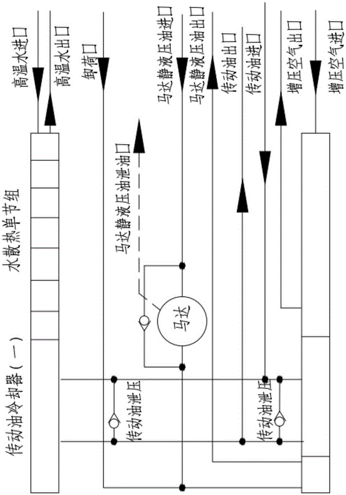
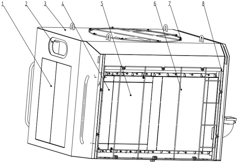
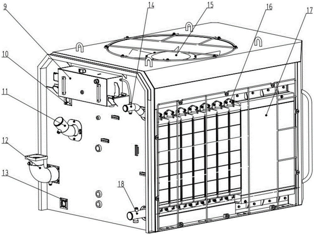
[0019] The invention unifies the cooling systems of the diesel locomotive into independent cooling chambers, which are directly installed on the chassis of the locomotive, so that the design of the cooling chamber can be carried out in parallel with the design of the car body, greatly reducing the interface data and shortening the production cycle. The engine water cooling system, charge air cooling system, transmission oil cooling system, hydraulic oil cooling system, cooling fan drive system, lighting system, expansion water tank 9, and hydrostatic oil tank are integrated in one cooling chamber. All cooling system components are integrated in a separate cooling chamber by means of a steel structure frame 3 . The cooling chamber is mounted directly on the locomotive chassis as a module of the diesel locomotive

[0020] The engine cooling water system mainly includes components such as a water cooling single-section group, an expansion tank 9, a collecting pipe, and water inle...


PUM


Abstract

The invention discloses a cooling room for an internal combustion locomotive. The cooling room serves as a module of the internal combustion locomotive to be directly installed on a locomotive chassis. The cooling room comprises a steel-structure frame, an engine water cooling system, a pressurized air cooling system, a transmission oil cooling system, a hydraulic oil cooling system, a cooling fan driving system, a lighting system and an external expansion water tank, wherein the engine water cooling system, the pressurized air cooling system, the transmission oil cooling system, the hydraulic oil cooling system, the cooling fan driving system and the lighting system are installed on the steel-structure frame. Liquid level observation, port connection and maintenance and detachment are facilitated. A transmission oil pressure relief pipeline and an overflow valve are arranged between a transmission oil inlet pipeline and a transmission oil outlet pipeline to prevent the damage, caused by system pressure fluctuation, runner congestion and other circumstances, to heat dissipation. A double-flow-path cooling structure is adopted in the transmission oil cooling system so that a transmission oil radiator can be arranged more flexibly and the structure of the cooling room can be more reasonable. A protection pipeline is arranged between a motor oil inlet pipeline and a motor oil outlet pipeline to mainly prevent the phenomenon that negative pressure is caused in the pipelines due to the fact that hydraulic oil supply is stopped at the moment of the machine halt, and consequently the pipelines are contracted and shrunk.

Description

technical field [0001] The invention relates to the technical field of cooling systems for diesel locomotives. Background technique [0002] Diesel locomotives have irreplaceable advantages in corresponding fields due to their independence from power grids and strong adaptability. They are mainly used in intercity transportation of non-electrified railways, freight transportation, and in-plant traction and shunting of industrial and mining enterprises. In modern locomotive design, modular design is usually adopted in order to improve product versatility, enhance maintainability and installability. For example, the locomotive is divided into modules such as power room, cooling room and control room for production. In view of emission requirements, diesel locomotives generally use supercharged diesel engines, and their cooling systems generally include diesel engine cooling water systems, charge air cooling systems, transmission oil cooling systems and hydrostatic cooling sys...

Claims


Application Information

Patent Timeline
Patent Type & Authority Applications(China)
IPC IPC(8): B61C17/00
CPCB61C17/00
Inventor 薛龙昌周美旺包明冬
Owner CRRC DALIAN INST CO LTD
Why Eureka
Try Eureka