Alloy type thermal link with breaking current resistance
A thermal fuse-link, current-disconnecting technology, used in circuits, electrical components, emergency protection devices, etc., can solve problems such as difficulty in meeting high-quality standards for home appliance companies, easy sparks, and overflow of low-melting-point alloys.
- Summary
- Abstract
- Description
- Claims
- Application Information
AI Technical Summary
Problems solved by technology
Method used
Image
Examples
Embodiment 1
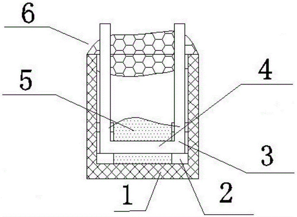
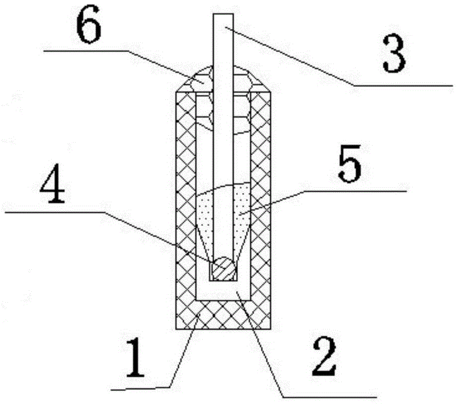
[0041] like Figure 1-2 As shown, an alloy-type thermal fuse with resistance to breaking current is composed of a housing 1, a lead wire 3, a heating element 4, a cosolvent 5 and an epoxy resin glue 6. The two sides of the inner bottom of the housing 1 are respectively A U-shaped positioning groove 2 is provided, and lead wires 3 are respectively installed in the U-shaped positioning grooves 2 on the left and right sides of the housing 1, and one end surface of the left and right two lead wires 3 is connected by a welded heating element 4, which is located at the bottom of the housing 1 A cosolvent 5 is filled around the central heating element 4; the other end of the lead wire 3 is exposed at the upper opening of the housing 1, and epoxy resin glue 6 is filled around the lead wire 3 at the opening of the housing 1. The glue 6 fixes the lead wire 3 on the housing 1 and seals the port of the housing 1 .
[0042]The shell 1 is composed of polyamide 66 (PA66) with 30% glass fibe...
Embodiment 2
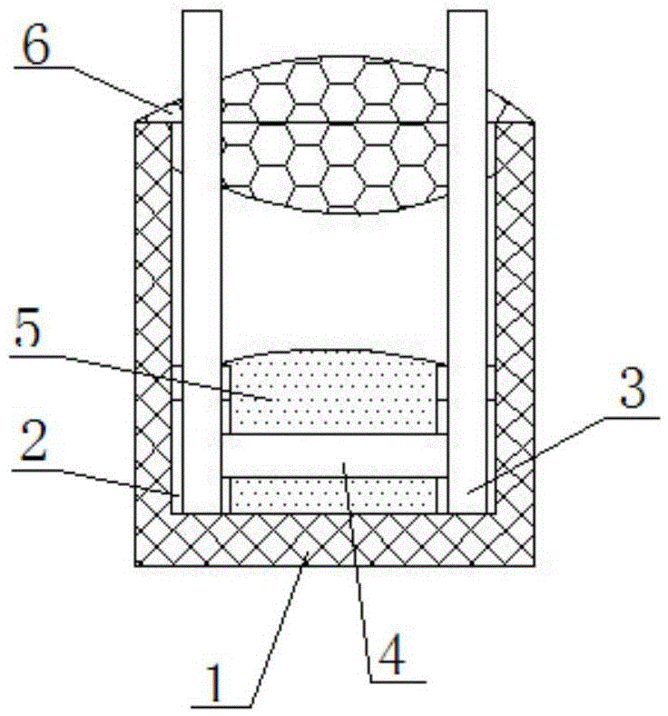
[0057] like Figure 3-4 As shown, an alloy-type thermal fuse with resistance to breaking current is composed of a housing 1, a lead wire 3, a heating element 4, a cosolvent 5 and an epoxy resin glue 6. The two sides of the inner bottom of the housing 1 are respectively A U-shaped positioning groove 2 is provided, and lead wires 3 are respectively installed in the U-shaped positioning grooves 2 on the left and right sides of the housing 1, and the lower ends of the left and right two lead wires 3 are connected by a welded thermal element 4. At this time, when the thermal element 4 is welded The overlapping point is not on the lower end surfaces of the two lead wires 3, the thermal element 4 is 0.6mm-1mm away from the lower end surfaces of the lead wires 3, the bottom thickness of the U-shaped positioning groove can be zero, and it is located around the thermal element 4 in the center of the bottom of the housing 1 The auxiliary solvent 5 is filled; the other end of the lead wir...
Embodiment 3
[0070] The mass percentage is: Sn50 mass parts, Bi30 mass parts, In20 mass parts alloy base material is made into a thermal element 4 with an outer diameter of Ф0.7mm or the same cross-sectional area. The surface of the thermal element 4 should be smooth, free of burrs, cracks, Bubbles, mechanical damage, no oil stains, stains, no corrosion;
[0071] Use resistance welding to weld the lead wire 3 on the heating element 4. The lead wire 3 is a high-quality soft tinned copper wire. There is no flux and other residues, and the heating element 4 has no cracks at the welding place;
[0072] Prepared with 83 parts by mass of rosin, 10 parts by mass of stearic acid, 1 part by mass of ethylene-vinyl acetate copolymer (abbreviated as EVA), 4 parts by mass of triethanolamine, 1 part by mass of castor oil, and 1 part by mass of di-n-octyl sebacate The flux 5 coats the thermal element 4 after soldering.
[0073] When preparing co-solvent 5, first slowly melt the rosin, and then mix in t...
PUM
| Property | Measurement | Unit |
|---|---|---|
| Bottom thickness | aaaaa | aaaaa |
| Diameter | aaaaa | aaaaa |
| Diameter | aaaaa | aaaaa |
Abstract
Description
Claims
Application Information
 - R&D
- Intellectual Property
- Life Sciences
- Materials
- Tech Scout
- Unparalleled Data Quality
- Higher Quality Content
- 60% Fewer Hallucinations
Browse by: Latest US Patents, China's latest patents, Technical Efficacy Thesaurus, Application Domain, Technology Topic, Popular Technical Reports.
© 2025 PatSnap. All rights reserved.Legal|Privacy policy|Modern Slavery Act Transparency Statement|Sitemap|About US| Contact US: help@patsnap.com


