An alloy type thermal fuse with breaking current resistance

A technology for disconnecting current and thermal fuse, applied in circuits, electrical components, emergency protection devices, etc., can solve problems such as difficulty in meeting high-quality standards of home appliance enterprises, easy to spray sparks, and overflow of low-melting-point alloys.

Active Publication Date: 2018-10-30
洪湖市蓝光电子有限责任公司
View PDF9 Cites 3 Cited by
  • Summary
  • Abstract
  • Description
  • Claims
  • Application Information

AI Technical Summary

Problems solved by technology

[0004] The purpose of the present invention is to provide a current-resistant, good fusing performance, high product quality, simple structure, easy production, safe use; solve the problem that the prior art is limited by the production material and material structure, which causes the existing alloy type heat The fuse link has insufficient resistance to breaking current, and it is easy to emit sparks, overflow low-melting point alloys or even burst and burn. It is difficult to meet the high-quality standards of home appliance companies.

Method used


Image

  • An alloy type thermal fuse with breaking current resistance
  • An alloy type thermal fuse with breaking current resistance
  • An alloy type thermal fuse with breaking current resistance

Examples


Embodiment 1

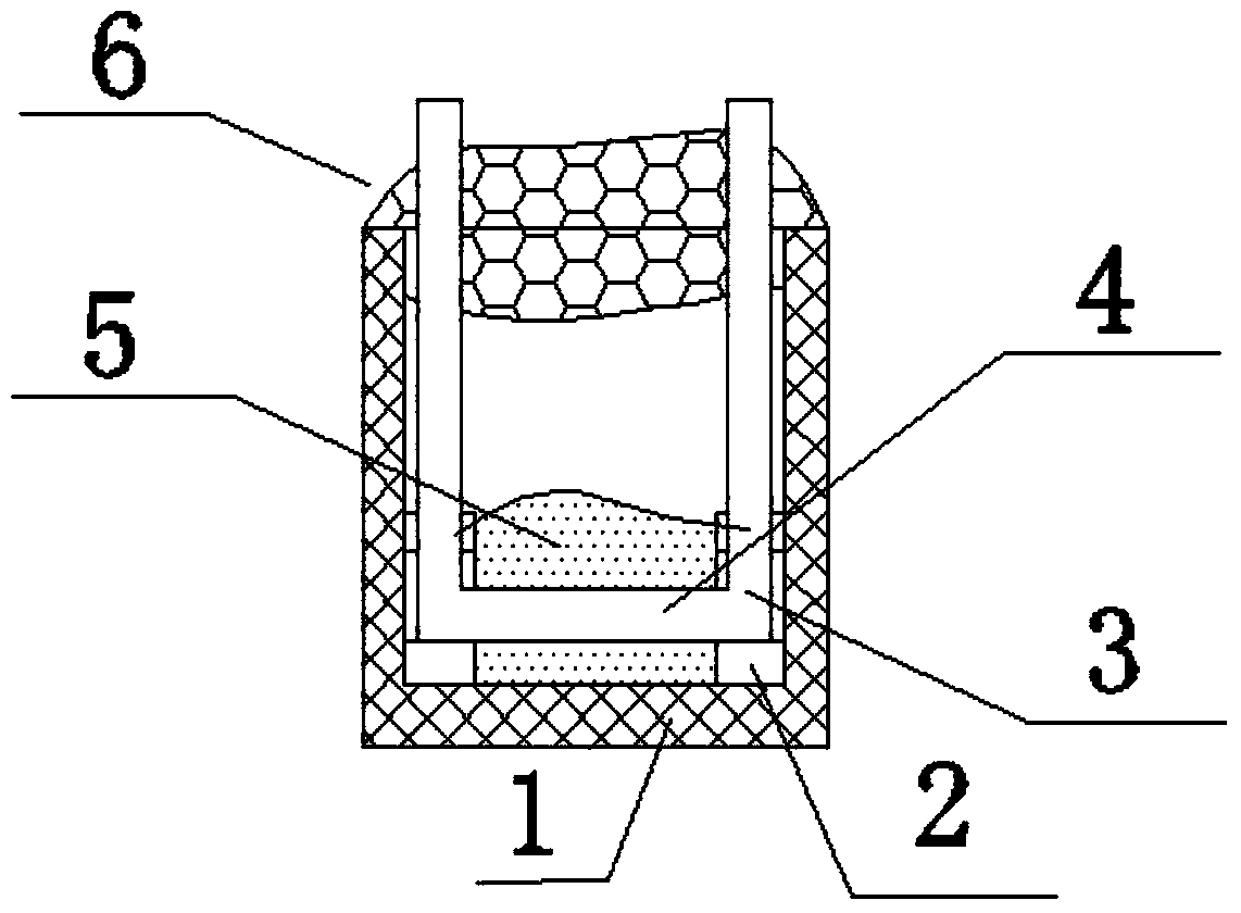
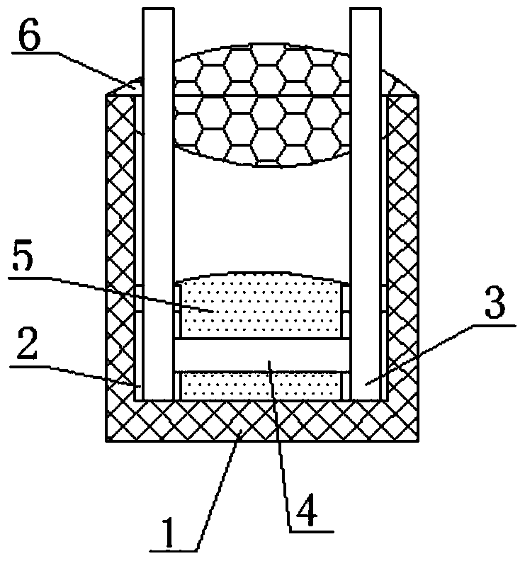
[0041] Such as Figure 1-2 As shown, an alloy-type thermal fuse with resistance to breaking current is composed of a housing 1, a lead wire 3, a heating element 4, a cosolvent 5 and an epoxy resin glue 6. The two sides of the inner bottom of the housing 1 are respectively A U-shaped positioning groove 2 is provided, and lead wires 3 are respectively installed in the U-shaped positioning grooves 2 on the left and right sides of the housing 1, and one end surface of the left and right two lead wires 3 is connected by a welded heating element 4, which is located at the bottom of the housing 1 A cosolvent 5 is filled around the central heating element 4; the other end of the lead wire 3 is exposed at the upper opening of the housing 1, and epoxy resin glue 6 is filled around the lead wire 3 at the opening of the housing 1. The glue 6 fixes the lead wire 3 on the housing 1 and seals the port of the housing 1 .

[0042]The shell 1 is composed of polyamide 66 (PA66) with 30% glass f...

Embodiment 2

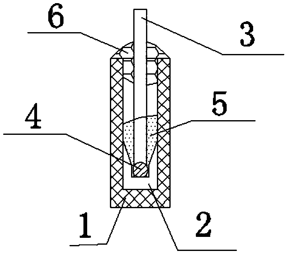
[0057] Such as Figure 3-4 As shown, an alloy-type thermal fuse with resistance to breaking current is composed of a housing 1, a lead wire 3, a heating element 4, a cosolvent 5 and an epoxy resin glue 6. The two sides of the inner bottom of the housing 1 are respectively A U-shaped positioning groove 2 is provided, and lead wires 3 are respectively installed in the U-shaped positioning grooves 2 on the left and right sides of the housing 1, and the lower ends of the left and right two lead wires 3 are connected by a welded thermal element 4. At this time, when the thermal element 4 is welded The overlapping point is not on the lower end surfaces of the two lead wires 3, the thermal element 4 is 0.6mm-1mm away from the lower end surfaces of the lead wires 3, the bottom thickness of the U-shaped positioning groove can be zero, and it is located around the thermal element 4 in the center of the bottom of the housing 1 The auxiliary solvent 5 is filled; the other end of the lead ...

Embodiment 3

[0070] The mass percentage is: Sn50 mass parts, Bi30 mass parts, In20 mass parts alloy base material is made into a thermal element 4 with an outer diameter of Ф0.7mm or the same cross-sectional area. The surface of the thermal element 4 should be smooth, free of burrs, cracks, Bubbles, mechanical damage, no oil stains, stains, no corrosion;

[0071] Use resistance welding to weld the lead wire 3 on the heating element 4. The lead wire 3 is a high-quality soft tinned copper wire. There is no flux and other residues, and the heating element 4 has no cracks at the welding place;

[0072] Prepared with 83 parts by mass of rosin, 10 parts by mass of stearic acid, 1 part by mass of ethylene-vinyl acetate copolymer (abbreviated as EVA), 4 parts by mass of triethanolamine, 1 part by mass of castor oil, and 1 part by mass of di-n-octyl sebacate The flux 5 coats the thermal element 4 after soldering.

[0073] When preparing co-solvent 5, first slowly melt the rosin, and then mix in t...


PUM

PropertyMeasurementUnit
diameteraaaaaaaaaa
diameteraaaaaaaaaa
thicknessaaaaaaaaaa

Abstract

The invention relates to an alloy type thermal link with breaking current resistance. The alloy type thermal link belongs to the technical field of manufacture of a fuse thermal link for electrical equipment. The alloy type thermal link comprises a housing, a lead wire, a thermal component, a cosolvent and an epoxy resin adhesive. Two sides of the bottom of the housing are respectively provided with a U-shaped positioning trough. Leads are inserted into the two U-shaped positioning troughs. One end of each of the two leads is welded with and is connected with the thermal component in an overlapping manner. Cosolvent is filled at the periphery of the thermal component. The height of a space between the thermal component and the bottom in the housing is 0.6mm-1.0mm. The other end of each of the two leads is exposed from the upper opening of the housing. The epoxy resin adhesive is filled at the periphery of the lead at the opening of the housing. The epoxy resin adhesive with a filler which has advantages of improving compactness, adjusting thermal expansion coefficient and improving high temperature resistance is added, thereby preventing corrosion of the thermal component by oxygen in the air. The self gravity function of the thermal component is used for improving breaking current resistance of the alloy type thermal link. The alloy type thermal link has advantages of high fusion performance, high product quality, simple structure, safe and convenient manufacture, and safe and convenient use.

Description

technical field [0001] The invention relates to an alloy-type thermal fuse with breaking current resistance, and belongs to the technical field of manufacturing thermal fuses for electrical equipment. Background technique [0002] Electrical appliances and electronic equipment are prone to overheating under fault conditions. Therefore, alloy type thermal fuses should be used for protection according to regulations, so as to avoid the high temperature from causing the circuit to catch fire and burn down electrical appliances and electronic equipment, causing fires that endanger people's lives and property safety. [0003] The production of alloy-type thermal fuses in the industry requires breaking current tests according to the national standard GB9816.1-2013, that is, under the specified conditions, a power factor of 0.60 and a voltage of 275VAC are applied, and the thermal fuse is tested at a test current of 1.5 times the rated current value of the breaking inductance. Afte...

Claims


Application Information

Patent Timeline
Patent Type & Authority Patents(China)
IPC IPC(8): H01H85/165H01H85/06H01H85/18
CPCH01H85/06H01H85/165H01H85/18
Inventor 吴峰刘身文陆先胜代柏林杨红英茹红英刘卫邓小红
Owner 洪湖市蓝光电子有限责任公司
Why Eureka
Try Eureka