
Optical voltage transformer

A technology of optical voltage and transformer, applied in the direction of voltage/current isolation, etc., can solve the problems of permanent damage of vacuum switch, overvoltage endangering the operation safety of electrical equipment, narrow linear range, etc., and achieve the elimination of magnetic saturation and ferromagnetic resonance, The overall structure is safe and reliable, and the effect of wide frequency response range

Inactive Publication Date: 2016-03-30
NR ELECTRIC CO LTD +1
View PDF9 Cites 5 Cited by
  • Summary
  • Abstract
  • Description
  • Claims
  • Application Information

AI Technical Summary

Problems solved by technology

[0004] (1) As the voltage level increases, the volume and weight of traditional voltage transformers double, the insulation structure is complex, and the cost increases;
[0005] (2) The electromagnetic voltage transformer has an inductance coil and ferromagnetic material, the frequency band is not wide enough, the linear range is narrow, and the saturation of the transformer core in the fault state limits its dynamic response accuracy;
[0006] (3) The transient signal generated may cause the malfunction of the fast protection device
The opening and closing of the transformer will generate voltage oscillation, causing permanent damage to the vacuum switch, and the entire measuring device of the voltage transformer has the risk of secondary short circuit;
[0007] (4) Ferromagnetic resonance may occur, and overvoltage may endanger the operation safety of electrical equipment
[0008] (5) The output signal cannot be directly interfaced with the computerized measurement and protection equipment

Method used


Image

  • Optical voltage transformer
  • Optical voltage transformer
  • Optical voltage transformer

Examples


Embodiment Construction

[0026] The technical solutions of the present invention will be described in detail below in conjunction with the accompanying drawings.

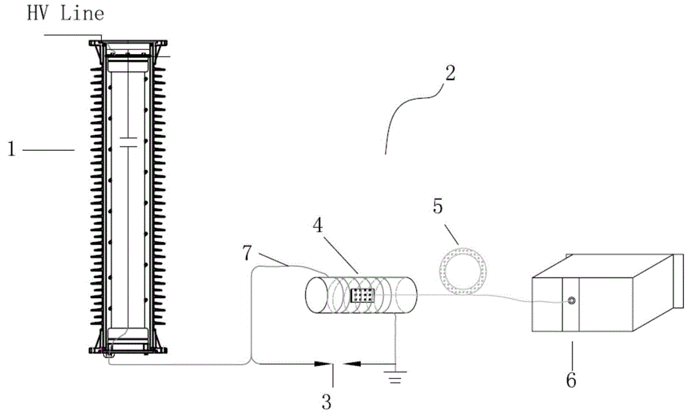
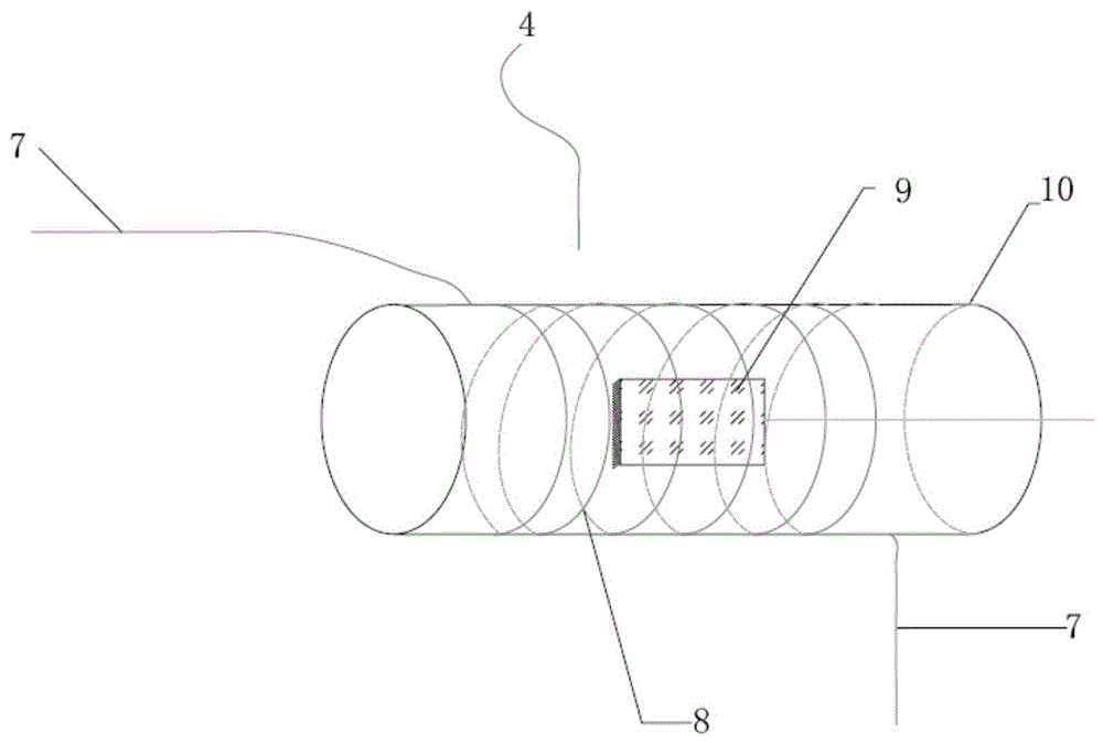
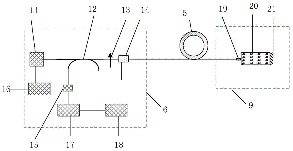
[0027] The optical voltage transformer of the present invention is composed of a voltage-current converter 1 , an optical small current sensor 2 and a protection gap 3 . The voltage-to-current converter 1 is realized by a high-voltage capacitor, which converts a high voltage into a small current; the optical small current sensor 2 is realized by a magneto-optic glass type optical current transformer, and consists of a magneto-optic glass type primary sensor 4, a transmission optical cable 5 and The acquisition unit 6 is composed of three parts; its magneto-optic glass-type primary sensor 4 senses the small current output by the voltage-current converter 1, and the transmission cable 5 connects the magneto-optic glass-type primary sensor 4 and the acquisition unit 6, and the acquisition unit 6 is located in the main control indoor or outdoor...


PUM


Abstract

The invention discloses an optical voltage transformer comprising a voltage-current converter, an optical low-current sensor, and a protection gap. The voltage-current converter is implemented by a high-voltage capacitor and converts primary high voltage into low current. The optical low-current sensor is implemented by a magneto-optic glass optical current transformer and is formed by a magneto-optic glass primary sensor, a transmission optical cable, and an acquisition unit. The magneto-optic glass primary sensor is a magneto-optic glass sensing probe disposed in a solenoid and induces the low current output by the voltage-current converter by means of a Faraday magneto-optic effect. The transmission optical cable is connected with the magneto-optic glass primary sensor and the acquisition unit. The acquisition unit is arranged in a master control chamber or an outdoor cabinet, demodulates a low-current signal induced by a magneto-optic glass optical current transformer optical path system, and outputs a digital signal, indicative of primary voltage, to be used by a relay protection device and a metering device.

Description

technical field [0001] The invention relates to an optical voltage transformer used in an AC substation, in particular to a high-voltage optical voltage transformer used in an intelligent substation with strong anti-electromagnetic interference capability. Background technique [0002] Voltage transformer is an important equipment for monitoring the operation status of power system. Measurement, monitoring and protection control devices in substations rely on it to obtain voltage information required for measurement, measurement and protection. [0003] At present, the power system mainly uses the traditional electromagnetic induction voltage transformer to realize the measurement of the voltage signal. With the improvement of the voltage level and capacity of the power system and the continuous improvement of measurement and protection requirements, the shortcomings of electromagnetic transformers have become increasingly prominent. The main problems include: [0004] (1) ...

Claims


Application Information

Patent Timeline
IPC IPC(8): G01R15/24
Inventor 阎嫦玲许立国丁晔李广宇王耀赵俊罗苏南须雷李响郎瑛
Owner NR ELECTRIC CO LTD
Learn More