Lithium ion liquid flow cell reactor

A liquid flow battery and lithium ion technology, applied in the direction of regenerative fuel cells, fuel cell components, etc., can solve problems such as inconsistent flow of electrode suspensions, deterioration of battery performance, overcharging or overdischarging of battery cells, and avoid disadvantages Influencing, improving safety, good diversion and confluence effects

Active Publication Date: 2016-03-30
南京竞予能源有限公司
View PDF6 Cites 16 Cited by
  • Summary
  • Abstract
  • Description
  • Claims
  • Application Information

AI Technical Summary

Problems solved by technology

This use of the splitter chamber to distribute the electrode suspension to multiple battery reaction chambers for reaction and then confluence through the confluence chamber often leads to inconsistent flow rates of the electrode suspension in each battery reaction chamber, which can easily cause the battery cells in the battery reactor to overcharge or overdischarge, deteriorating battery performance

Method used


Image

  • Lithium ion liquid flow cell reactor
  • Lithium ion liquid flow cell reactor
  • Lithium ion liquid flow cell reactor

Examples


Embodiment 1

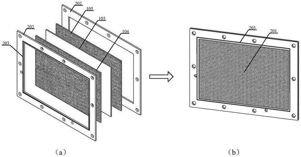
[0050] This embodiment provides a lithium ion flow battery reactor 601 , which includes a bipolar separator 201 , a positive electrode conductor 301 a , a negative electrode conductor 301 b , an upper cover plate 602 , and a lower cover plate 603 . Among them, several bipolar separators 201, positive electrode conductors 301a, and negative electrode conductors 301b are alternately stacked up and down to form a battery cell group 501, and the lithium ion flow battery reactor 601 follows the upper cover plate 801—the battery cell group 601— The lower cover plate 802 is arranged in a manner, sealed by a seal, and compressed by a fastener. The respective battery cells 501 are connected in parallel by metal wires.

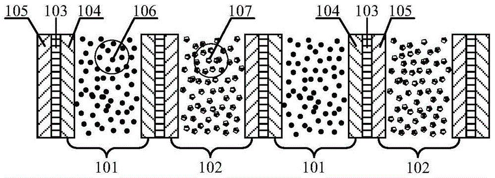
[0051] In this embodiment, the bipolar separator 201 is composed of the isolation layer 103 and the positive electrode current collector layer 104 and the negative electrode current collector layer 105 which are located on both sides of the isolation layer and are in cl...

Embodiment 2

[0058] In this embodiment, the bipolar separator 201 is composed of a separation layer 103 and a positive current collector layer 104 and a negative current collector layer 105 located on both sides of the separation layer 103 and in close contact with the separation layer 103 . Wherein, the isolation layer 103 is an electronic insulating layer that isolates the positive and negative current collector layers and prevents the electrons in the battery from freely passing through, but the lithium ions in the electrolyte or gel electrolyte can freely pass through, and its thickness is 0.5 mm. Both the positive electrode current collecting layer 104 and the negative electrode current collecting layer 105 are ion / electron mixed conductive layers through which both lithium ions and electrons can pass freely, and both have a thickness of 0.5 mm. The positive electrode current collector layer 104 and the negative electrode current collector layer 105 are placed on both sides of the isol...

Embodiment 3

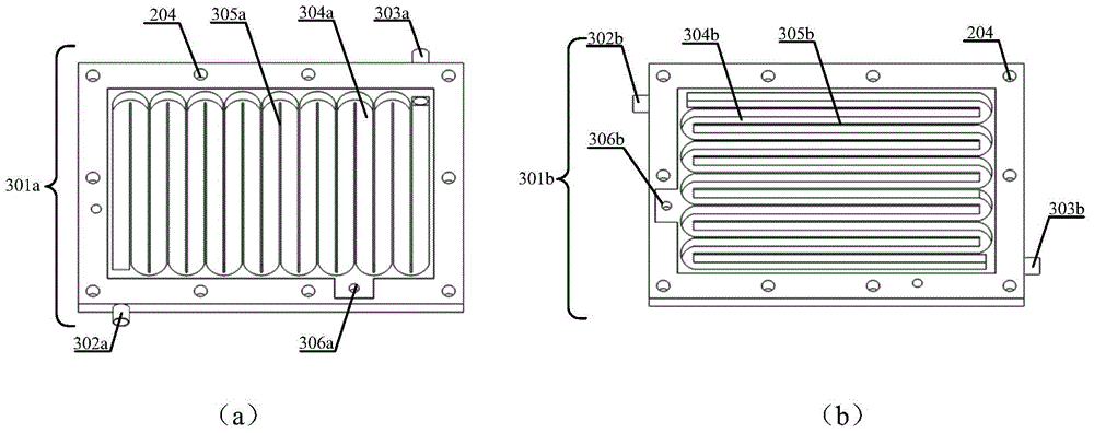
[0068] In this embodiment, the positive electrode flow channel ridge 305a is located in the positive electrode reaction chamber and can resist oxidation reaction. The material is one or more of aluminum, alloy aluminum, stainless steel, silver, tin or titanium, preferably aluminum; 305b is located in the negative electrode reaction chamber and is resistant to reduction reaction. The material is one or more of copper, stainless steel, nickel, titanium, silver, tin, tin-plated copper, nickel-plated copper, and silver-plated copper, preferably nickel-plated stainless steel;

[0069] Alternatively, the positive electrode runner ridge 305a and the negative electrode runner ridge 305b are electronically conductive films coated on the surface of organic fiber materials; the organic fiber materials include polyester fibers, nylon fibers, natural cotton, aramid, nylon, polypropylene, Polyethylene, polytetrafluoroethylene and other organic substances with good electrolyte resistance; the...


PUM

PropertyMeasurementUnit
heightaaaaaaaaaa
widthaaaaaaaaaa
heightaaaaaaaaaa

Abstract

The invention provides a lithium ion liquid flow cell reactor including a bipolar diaphragm, a positive electrode diversion body and a negative electrode diversion body; each diversion body is formed by arranging a continuous diversion channel in a hollow rectangular-ambulatory-plane frame, the border of the positive electrode diversion body is provided with a positive electrode liquid inlet and a positive electrode liquid outlet, the border of the negative electrode diversion body is provided with an negative electrode liquid inlet and an negative electrode liquid outlet, and the liquid inlet and the liquid outlet of each diversion body communicate through the diversion channel in the diversion body; according to the cell reactor, each cell reaction cavity is provided with one liquid inlet and one liquid outlet, the liquid inlets and the liquid outlets adopt a parallel mode, or a series mode, or a series and parallel mixed mode, so that uniform and consistent shunting and confluence of the lithium ion liquid flow cell reactor are achieved, a shunt cavity and a confluence cavity are omitted, and thus the consistency between the cell units is effectively increased, the cell performance is improved, and the structure of the reactor is greatly simplified.

Description

technical field [0001] The invention belongs to the field of chemical energy storage batteries, in particular to a lithium ion flow battery reactor. Background technique [0002] Lithium-ion flow battery is a newly developed electrochemical battery technology. It combines the advantages of lithium-ion battery and flow battery. It is a kind of output power and energy storage capacity independent of each other, with high energy density and low cost new secondary battery. It can not only be used as a supporting energy storage device for solar and wind power generation systems, but also as a peaking device for the power grid to improve the quality of power transmission and ensure the safety of the power grid. The use of chemical power sources for electrical storage and energy storage is not limited by geographical conditions, and it is expected to achieve large-scale energy storage, which has great social and economic value. [0003] In the previous lithium-ion flow battery re...

Claims


Application Information

Patent Timeline
Patent Type & Authority Applications(China)
IPC IPC(8): H01M8/18H01M8/02
CPCY02E60/50
Inventor 陈永翀张晓虎张艳萍张萍
Owner 南京竞予能源有限公司
Why Eureka
Try Eureka