Flue gas treatment technology and apparatus thereof
A technology of flue gas treatment and process, which is applied in the field of flue gas treatment process and equipment, can solve the problems of complex operation and low efficiency, and achieve the effects of easy popularization and application, improved efficiency, and less cumbersome operation steps
- Summary
- Abstract
- Description
- Claims
- Application Information
AI Technical Summary
Problems solved by technology
Method used
Image

Examples
Embodiment 1
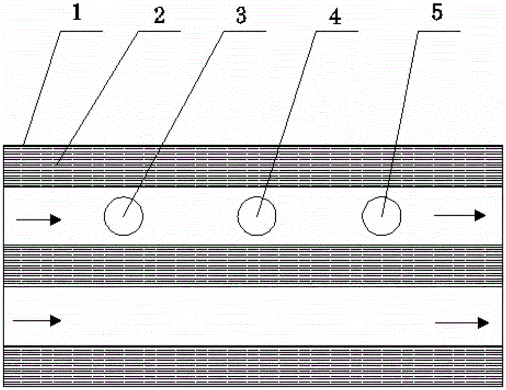
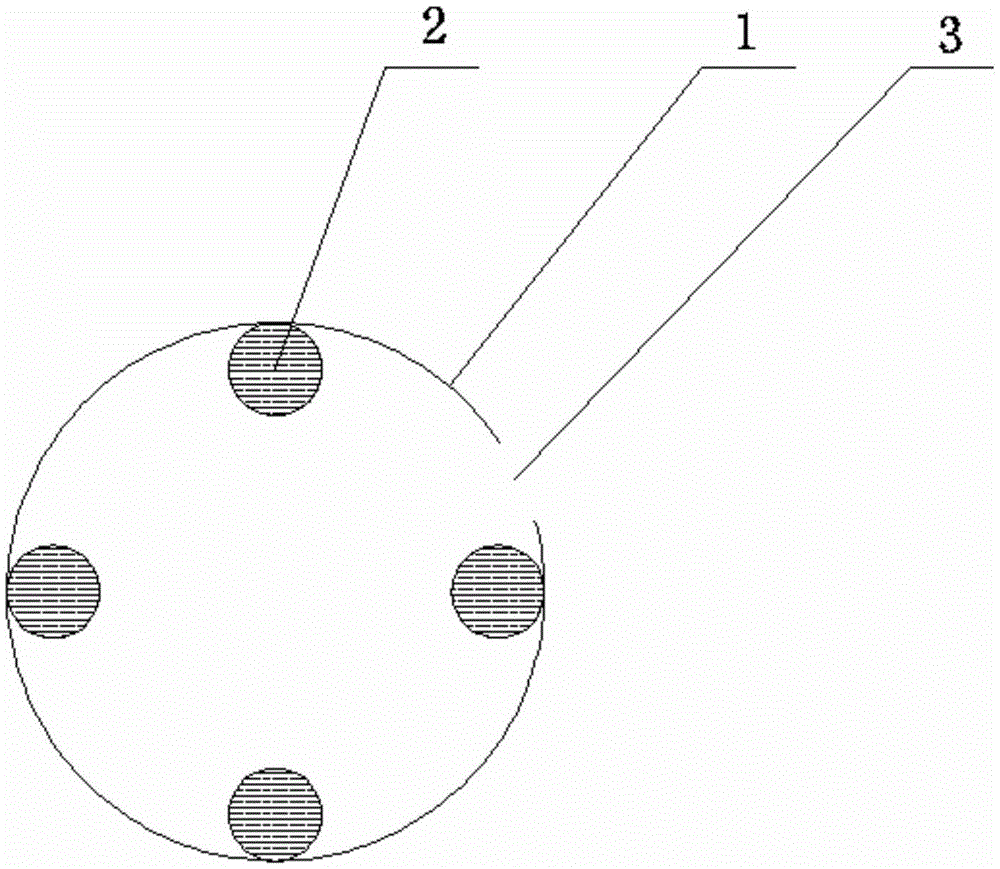
[0022] A flue gas treatment process, comprising the following steps: turn on the switch of the ultraviolet lamp (2), make the ultraviolet lamp (2) in the working state, pass the flue gas with a temperature of 60°C through the flue gas pipe (1), and simultaneously pass through the The hydrogen peroxide inlet (3) is sprayed into the atomized hydrogen peroxide solution, oxygen is introduced through the oxygen inlet (4), the atomized solution A is sprayed into the solution A inlet (5), and mixed with the flue gas; Solution A is composed of a copper sulfate solution with a concentration of 10ppm and a magnesium sulfate solution with a concentration of 10ppm according to a volume ratio of 1:2.
[0023] The ultraviolet wavelength of the ultraviolet lamp (2) is 180nm.
[0024] The concentration of the hydrogen peroxide solution is 15ppm.
[0025] The oxygen is pure oxygen, and the concentration of oxygen in the flue gas pipeline (1) is controlled to be 0.05mol / L.
[0026] The device...
Embodiment 2
[0030] A flue gas treatment process, comprising the following steps: turn on the switch of the ultraviolet lamp (2), put the ultraviolet lamp (2) in a working state, pass the flue gas with a temperature of 70°C through the flue gas pipe (1), and simultaneously pass through the The hydrogen peroxide inlet (3) is sprayed into the atomized hydrogen peroxide solution, oxygen is introduced through the oxygen inlet (4), the atomized solution A is sprayed into the solution A inlet (5), and mixed with the flue gas; Solution A is composed of copper sulfate solution with a concentration of 15ppm and magnesium sulfate solution with a concentration of 5ppm according to the volume ratio of 1:2.
[0031] The ultraviolet wavelength of the ultraviolet lamp (2) is 260nm.
[0032] The concentration of the hydrogen peroxide solution is 20ppm.
[0033] The purity of the oxygen is 99.5%, and the concentration of the oxygen in the flue gas pipeline (1) is controlled to be 0.1mol / L.
[0034] The d...
Embodiment 3
[0038] A flue gas treatment process, comprising the following steps: turn on the switch of the ultraviolet lamp (2), make the ultraviolet lamp (2) in a working state, pass the flue gas with a temperature of 65°C through the flue gas pipe (1), and simultaneously pass through the The hydrogen peroxide inlet (3) is sprayed into the atomized hydrogen peroxide solution, oxygen is introduced through the oxygen inlet (4), and the atomized solution A is sprayed through the solution A inlet (5), mixed with the flue gas; Solution A is composed of a copper sulfate solution with a concentration of 12ppm and a magnesium sulfate solution with a concentration of 7ppm in a volume ratio of 1:2.
[0039] The ultraviolet wavelength of the ultraviolet lamp (2) is 200nm.
[0040] The concentration of the hydrogen peroxide solution is 18ppm.
[0041] The purity of the oxygen is 99.5%, and the concentration of the oxygen in the flue gas pipeline (1) is controlled to be 0.06mol / L.
[0042] The devi...
PUM
| Property | Measurement | Unit |
|---|---|---|
| Wavelength | aaaaa | aaaaa |
| Wavelength | aaaaa | aaaaa |
| Wavelength | aaaaa | aaaaa |
Abstract
Description
Claims
Application Information
 - R&D
- Intellectual Property
- Life Sciences
- Materials
- Tech Scout
- Unparalleled Data Quality
- Higher Quality Content
- 60% Fewer Hallucinations
Browse by: Latest US Patents, China's latest patents, Technical Efficacy Thesaurus, Application Domain, Technology Topic, Popular Technical Reports.
© 2025 PatSnap. All rights reserved.Legal|Privacy policy|Modern Slavery Act Transparency Statement|Sitemap|About US| Contact US: help@patsnap.com