
3D laser printing system and method based on robot

A 3D printing and laser printing technology, applied in the field of 3D metal printing, can solve the problems of undisclosed robot specific structure, undisclosed robot specific structure, undisclosed specific structure of laser grid positioning device, etc. The effect of less powder and reduced robot load

Inactive Publication Date: 2016-04-20
CANGZHOU DWAYA LASER TECH CO LTD
View PDF9 Cites 18 Cited by
  • Summary
  • Abstract
  • Description
  • Claims
  • Application Information

AI Technical Summary

Problems solved by technology

[0007] The Chinese patent No. 201310376201.7 discloses "a 3D printing robot based on an industrial manipulator". Its structure is that a 3D printing head is arranged at the front end of a multi-axis manipulator, and a laser grid positioning device is used for positioning, but the laser grid is not disclosed. The specific structure of the positioning device, but also did not disclose the specific structure of the robot, and the working process of the robot
[0008] The Chinese patent No. 201510427361.9 discloses "a 3D printing welding method using a multi-degree-of-freedom robot". Welding is performed according to the weld path pattern, etc., not the overall printing of parts, and the patent document does not disclose the specific structure of the robot.

Method used


Image

  • 3D laser printing system and method based on robot
  • 3D laser printing system and method based on robot
  • 3D laser printing system and method based on robot

Examples


Embodiment Construction

[0037] The present invention will be described in detail below in conjunction with the accompanying drawings, but it should be pointed out that the implementation of the present invention is not limited to the following embodiments.

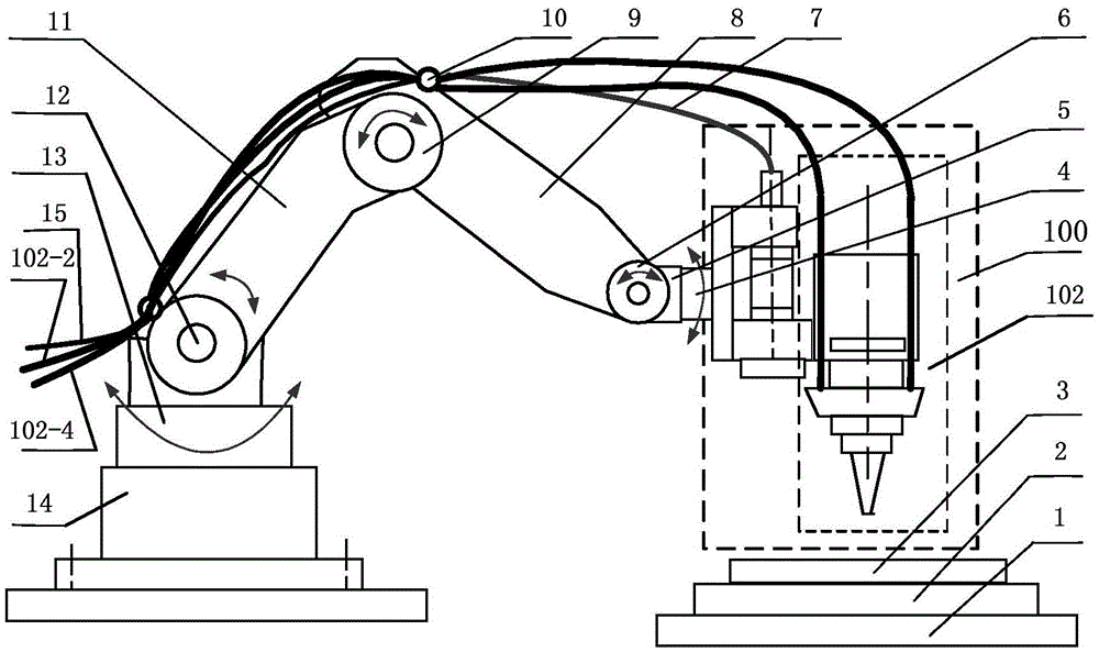
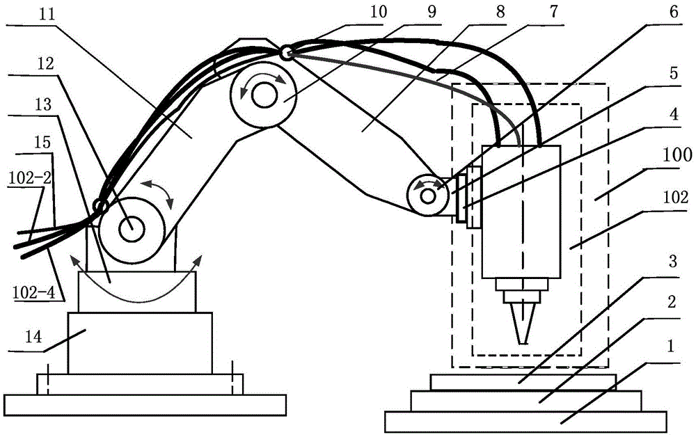
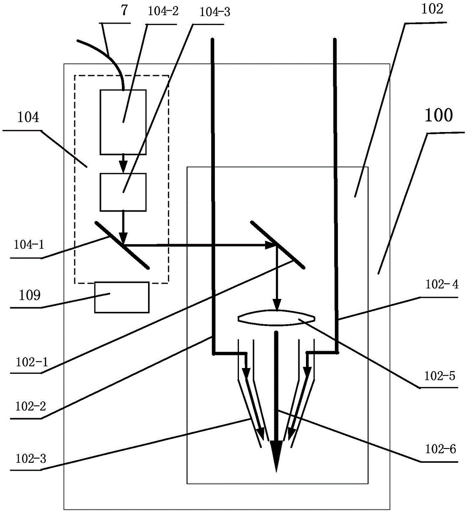
[0038] See Figure 1-Figure 8, a robot laser 3D printing system, using a mechanical arm to drive a laser print head unit 100 for 3D printing, the mechanical arm includes a machine base 14, a horizontal rotary disk, an arm joint 12, a large arm 11, an elbow joint 9, and a small arm 8. Wrist joint 6, robot wrist 5, connection plate 4, protective gas supply pipeline 102-4, powder supply pipeline 102-2 connected to the powder silo, the base 14 is provided with a horizontal rotary disc, and the horizontal rotary disc An arm joint 12 is fixed on the top, and the horizontal rotary disk drives the arm joint 12 to rotate. One end of the large arm 11 is articulated with the horizontal rotary disk through the arm joint 12, and the other end of the large arm...


PUM


Abstract

The invention relates to a 3D laser printing system and method based on a robot. A mechanical arm is utilized for driving a laser printing head unit for 3D printing, and comprises a machine base, a horizontal rotating disc, an arm joint, an upper arm, an elbow joint, a lower arm, a wrist joint, a robot wrist, a connecting disc, a protection gas supply pipeline, and a powder supply pipeline connected with a powder stock bin. The connecting disc is connected with the laser printing head unit, the connecting disc drives the laser printing head unit to rotate, and the protection gas supply pipeline and the powder supply pipeline are fixed to the upper arm and the lower arm through fixing rings. The end of the protection gas supply pipeline and the end of the powder supply pipeline are connected with the laser printing head unit. The 3D laser printing system and method have the advantages that metal parts, especially stainless steel alloy parts, in any shape can be directly machined and manufactured, and the machining and manufacturing efficiency of the metal parts, especially the stainless steel alloy parts, in the complex shapes is greatly improved. Adopted metal powder is directly sprayed according to the shapes of the parts, and little powder is left, and can be recycled and reused.

Description

technical field [0001] The invention relates to the field of 3D metal printing, in particular to a robot laser 3D printing system and method. Background technique [0002] 3D printing is a rapid prototyping technology, also known as rapid prototyping (RPM) technology, which was born in the late 1980s. It is an efficient manufacturing technology based on the direct sintering and accumulation method of materials. A major innovation. It integrates mechanical engineering, CAD, reverse engineering technology, layered manufacturing technology, numerical control technology, material science, and laser technology, and can automatically, directly, quickly and accurately transform design ideas into prototypes with certain functions or directly manufacture parts , so as to provide a high-efficiency and low-cost solution for the production of prototype parts and the verification of new design ideas. That is, rapid prototyping technology is to use the data of three-dimensional CAD to a...

Claims


Application Information

Patent Timeline
Patent Type & Authority Applications(China)
IPC IPC(8): B22F3/105B33Y30/00B33Y10/00
CPCB22F3/003B22F2203/00B22F10/00B22F12/90B22F12/44B22F12/49B22F10/25B22F12/46B22F12/70Y02P10/25
Inventor 王春岩卢青
Owner CANGZHOU DWAYA LASER TECH CO LTD
Learn More