Cryogenic separation recycling system and method for exhausted polyolefin flare gas

A cryogenic separation and recovery system technology, which is applied in refrigeration, liquefaction, liquefaction, solidification, etc., can solve problems such as the decline in the recovery rate of hydrocarbons, the damage of the rotor of the turbo expander, and the low pressure of the tail gas at the expansion outlet, and achieve the ultimate goal. The effect of optimizing the design

Active Publication Date: 2016-04-20
TECHNICAL INST OF PHYSICS & CHEMISTRY - CHINESE ACAD OF SCI +1
View PDF10 Cites 8 Cited by
  • Summary
  • Abstract
  • Description
  • Claims
  • Application Information

AI Technical Summary

Problems solved by technology

From the perspective of membrane separation tail gas recovery, the above method has obvious advantages, but in a larger range (that is, the overall polyolefin exhaust gas recovery system), its limitations are also obvious
First, the cooling capacity that can be obtained by the system is limited by the operating conditions of the membrane separation tail gas and the requirements for the exhaust gas at the expansion outlet. If the pressure of the membrane separation tail gas is low or the pressure of the expansion outlet gas is high, the cooling capacity will be insufficient, thus As a result, the recovery rate of hydrocarbons decreases, and the space for operation is small; secondly, the pressure of the tail gas at the expansion outlet is low, which makes further recovery difficult. For example, when using PSA technology to recover hydrogen or nitrogen in the tail gas, it is necessary to add a compressor; Third, the pressure of the recovered hydrocarbons is relatively low. If it is returned to the reaction system, a compressor needs to be added when the recovery is in the gas phase, and a compressor and a heat exchanger need to be added when the recovery is in gas-liquid two-phase; Fourth, The production process, product brand adjustment and the diversity of exhaust gas sources lead to frequent fluctuations in the working conditions of the flare gas, which puts pressure on the long-term stable operation of the entire device. This is because the turbo expander rotates at tens of thousands of rpm. When flow or pressure fluctuations lead to large changes in speed, it is easy to cause damage to the rotor of the turboexpander
To sum up, the methods provided by patents CN202485331U and CN103520946B are effective only when the tail gas is directly exhausted to the flare after expansion, and the recovered hydrocarbons are used as fuel, and the manufacturer’s requirements on the recovery rate of hydrocarbons are not too high. Advantages; on the contrary, although the recovery of membrane separation tail gas itself does not require power equipment, but more power equipment may need to be added downstream, the overall energy consumption and investment are not low

Method used


Image

  • Cryogenic separation recycling system and method for exhausted polyolefin flare gas
  • Cryogenic separation recycling system and method for exhausted polyolefin flare gas
  • Cryogenic separation recycling system and method for exhausted polyolefin flare gas

Examples


Embodiment

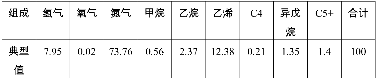
[0038] The exhaust gas of a full-density polyethylene production unit in a petrochemical company is recovered by compression and condensation, and the tail gas is discharged to the flare. The pressure range is 1.1~1.6 (typically 1.3) MPa(G), the temperature range is -15~0 (typically -10)°C, and the flow rate is 900~1200 (typically 1045) Nm3 / h.

[0039] Table 1 The measured value of the composition of the flare gas (v%)

[0040]

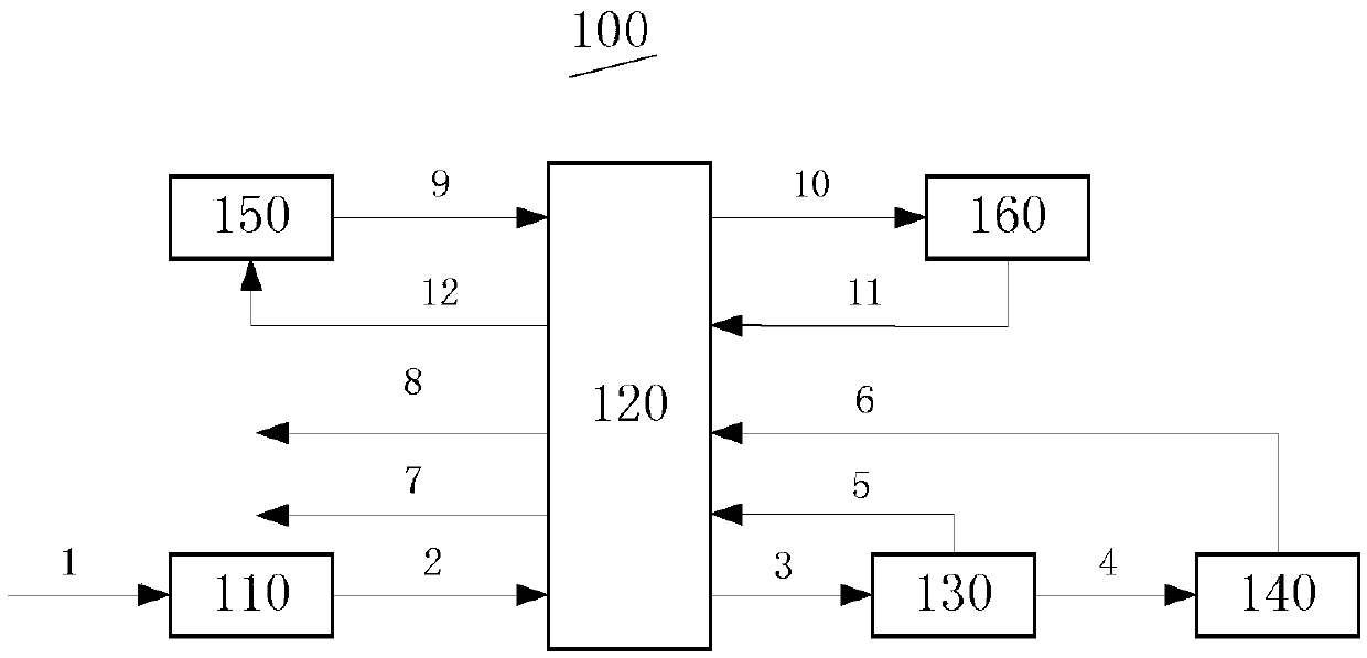
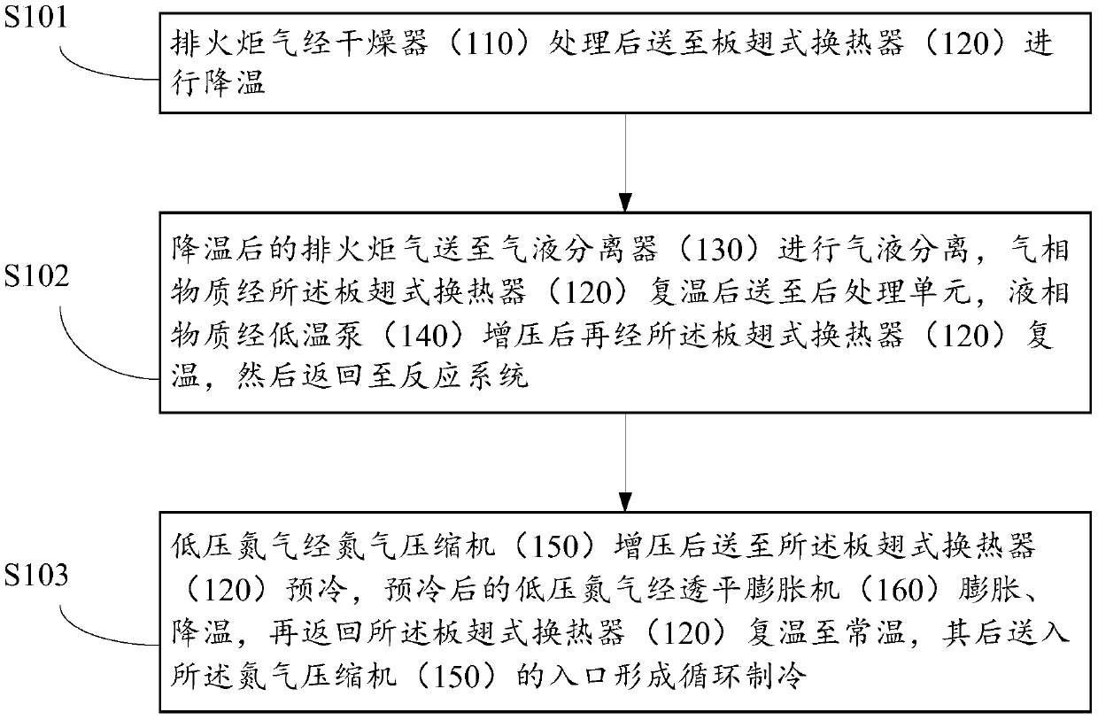
[0041] The exhaust torch gas (stream 1) first enters the dryer 110 for treatment, and when the dew point reaches about -70°C, it is sent to the plate-fin heat exchanger 120, and the temperature drops to -120°C step by step, and then sent to the gas-liquid separator 130, The separated gaseous substances are reheated by the plate-fin heat exchanger 120 and sent out of the boundary area (stream 7); the separated liquid-phase substances are pressurized to 3.2 MPa (G) by the cryopump, and then rewarmed by the plate-fin heat exchanger Then sent to the r...


PUM


Abstract

The invention provides a cryogenic separation recycling system for exhausted polyolefin flare gas. The system comprises a dryer (110) communicated to a plate-fin heat exchanger (120), a gas-liquid separator (130), a cryopump (140), a nitrogen compressor (150) and a turbo expander (160); the exhausted flare gas is processed through the dryer (110), the dried exhausted flare gas is delivered to the plate-fin heat exchanger (120) to be cooled and then delivered to the gas-liquid separator (130) for gas-liquid separation, a gas phase is reheated by the plate-fin heat exchanger (120) and then delivered to a postprocessing unit, and a liquid phase is pressurized by the cryopump (140) and then reheated by plate-fin heat exchanger (120) to return to a reaction system; low-pressure nitrogen is pressurized by the nitrogen compressor (150) and then delivered to the plate-fin heat exchanger (120) to be precooled, the precooled nitrogen is expanded and cooled by the turbo expander (160) and then returns to the plate-fin heat exchanger (120) to be reheated to the normal temperature, and the reheated nitrogen is delivered to an inlet of the nitrogen compressor (150) to form circulating refrigerating. Hydrocarbon substances in the exhausted flare gas can be maximumly recycled, so that the downstream can conveniently utilize the exhausted flare gas.

Description

technical field [0001] The invention relates to the field of environmental protection technology in the petrochemical industry, in particular to a cryogenic separation and recovery system and method for polyolefin exhaust torch gas. Background technique [0002] Polyolefin is a polymer compound formed by addition polymerization of many identical or different simple olefin molecules (such as ethylene, propylene, 1-butene, 1-pentene, etc.), among which polyethylene and polypropylene are the most important. Due to the abundance of raw materials, low price, easy processing and molding, and excellent comprehensive properties, polyolefins are widely used in various fields of production and life. Polyolefin production methods include high-pressure polymerization and low-pressure polymerization (including solution method, slurry method, bulk method, and gas phase method). [0003] There is usually a common problem in the production of polyolefins, that is, a large amount of exhaust...

Claims


Application Information

Patent Timeline
Patent Type & Authority Applications(China)
IPC IPC(8): F25J3/02
CPCF25J3/0257
Inventor 任小坤胡玉生唐守胜高元景徐晓亮张武
Owner TECHNICAL INST OF PHYSICS & CHEMISTRY - CHINESE ACAD OF SCI
Why Eureka
Try Eureka