Patch antenna unit and antenna

A patch antenna and radiation patch technology, which is applied in antennas, resonant antennas, antenna arrays, etc., can solve problems such as large area and poor antenna characteristics

Active Publication Date: 2016-05-04
HUAWEI TECH CO LTD
View PDF4 Cites 51 Cited by
  • Summary
  • Abstract
  • Description
  • Claims
  • Application Information

AI Technical Summary

Problems solved by technology

[0007] In this prior art, since the feeding method is fed by the second layer, the bandwidth is only about 4.6GHz in terms of return loss -10dB, and the return loss of the antenna at 65GHz is only -7dB, which is used because the antenna gain is low 16 patch antennas to increase the gain, which not only makes the area large, but also the antenna characteristics are not good

Method used


Image

  • Patch antenna unit and antenna
  • Patch antenna unit and antenna
  • Patch antenna unit and antenna

Examples


Embodiment Construction

[0039]In order to make the objectives, technical solutions and advantages of the present invention clearer, the present invention will be further described in detail below with reference to the accompanying drawings. Obviously, the described embodiments are only a part of the embodiments of the present invention, not all of the embodiments. Based on the embodiments of the present invention, all other embodiments obtained by persons of ordinary skill in the art without creative efforts shall fall within the protection scope of the present invention.

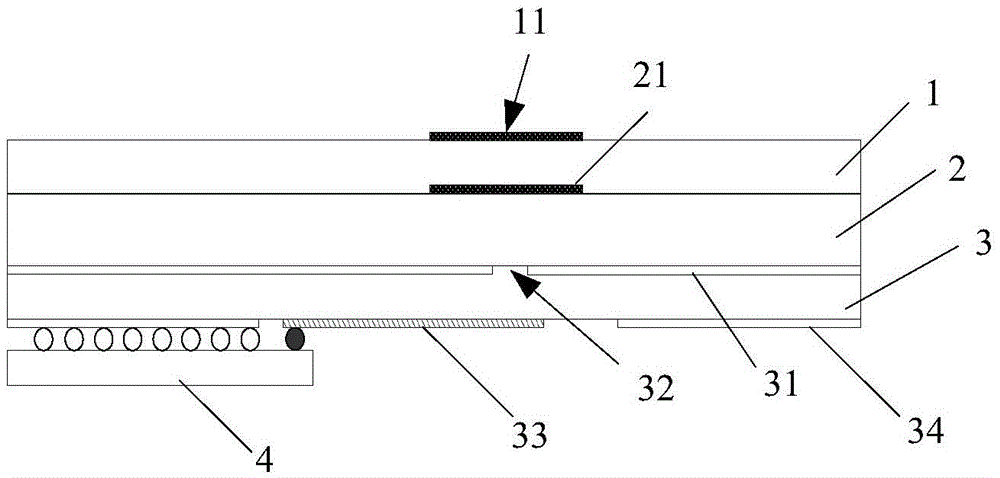
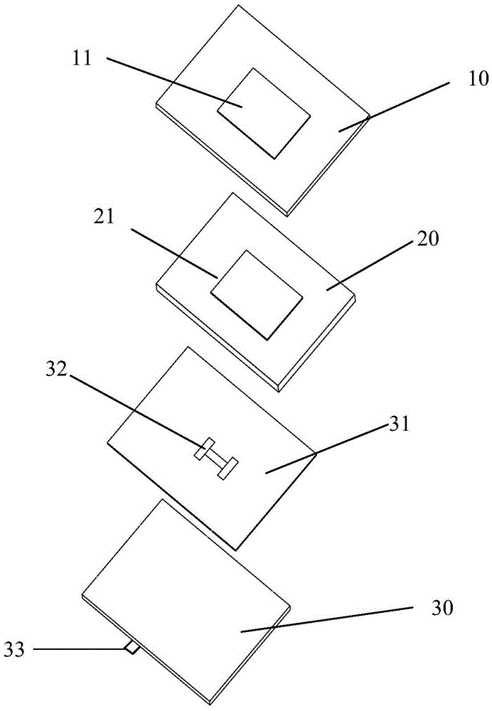
[0040] An embodiment of the present invention provides a patch antenna unit. The patch antenna unit includes a first support layer, and a substrate stacked with the first support layer is disposed on a side of the substrate away from the first support layer. The second support layer is provided on the integrated circuit on the side of the second support layer away from the substrate, wherein,

[0041] A first radiation patch is at...


PUM


Abstract

The invention relates to the technical field of communication, and discloses a patch antenna unit, an antenna and communication equipment. The patch antenna unit comprises stacked first support layer, substrate, second support layer and integrated circuit, wherein radiation patches are attached to the first support layer and the second support layer respectively; ground layers are arranged on the second support layer and are provided with coupling gaps; a feeder line corresponding to the coupling gaps is arranged on the second support layer; and the integrated circuit is connected with the first ground layers and the feeder line respectively. In a specific technical scheme, fabrication is carried out by the four layer-substrate, so that a 57-66GHz full-band high-frequency signal can be effectively fed into upper two layers of antennas for radiation by the coupling gaps in the third layer; the parasitic effect is reduced; meanwhile, the effective area of the antenna is increased by the stacked structure; and the performance effects of a high bandwidth and a high gain are brought for the antenna by achieved low parasitic parameters and high effective area.

Description

technical field [0001] The present invention relates to the technical field of communications, and in particular, to a patch antenna unit and an antenna. Background technique [0002] At present, the application of the 60GHz frequency band in the wireless personal communication system (WPAN: wirelesspersonalareanetwork) has aroused everyone's interest, mainly because everyone needs a larger bandwidth above 7GHz. The large bandwidth and the demand for millimeter waves do face many challenges in the design of microwave terminal applications. Generally, 60GHz wireless front-end products are usually completed with expensive GaAs microwave integrated circuits. To achieve the goal of low price, some are completed with silicon germanium-based circuits. These front-end products generally use the antenna and the die together, and some use multiple modules to include the antenna in the package (system in Chip, systemonchip). In this 60GHz application, the antenna has become a very i...

Claims


Application Information

Patent Timeline
Patent Type & Authority Applications(China)
IPC IPC(8): H01Q1/38H01Q1/48H01Q9/04
CPCH01Q1/48H01Q1/38H01Q1/50H01Q23/00H01Q1/2283H01Q9/0457H01Q21/0075H01Q21/065H01Q9/0414H01Q21/08H01Q9/045
Inventor 刘亮胜李信宏符会利
Owner HUAWEI TECH CO LTD
Why Eureka
Try Eureka