Radial flow by-product steam isothermal shift converter

A technology of isothermal transformation and by-product steam, applied in the field of temperature transformation furnace, can solve the problems of high equipment cost, high material consumption, high sealing and high cost, and achieve the requirements of low temperature application range, uniform temperature distribution and low equipment cost. Effect

Inactive Publication Date: 2016-05-11
INNOVATIVE COAL CHEMICAL DESIGN INSTITUTE (SHANGHAI) CO LTD
View PDF7 Cites 6 Cited by
  • Summary
  • Abstract
  • Description
  • Claims
  • Application Information

AI Technical Summary

Problems solved by technology

[0007] 1. The reaction temperature in the shift furnace is not easy to control, and the heat of reaction released during the reaction cannot be withdrawn in time, which will cause overburning of the catalyst, and the conversion rate of the first stage of the shift furnace is low;
[0008] 2. The height of the catalyst bed is high, and the resistance drop of the synthesis reaction is large. The more units in series, the greater the resistance drop, and the greater the energy consumption. The total pressure drop of the three series series system is as high as 0.5-0.8 MPa;
[0009] 3. Due to the structural characteristics of the adiabatic reaction, the metal temperature of the pressurized shell of the equipment is high, the thickness of the pressurized shell is thick, the requirements for materials are high, and the equipment cost is expensive
Its disadvantages are: the raw material gas of the device enters upward, and the converted gas after reaction also exits upward, the gas flow direction is U-shaped, and the resistance is large; the lower part adopts a large flange to clamp the integral tube plate, which consumes a lot of materials; the expansion joint of the gas collection pipe is set Due to the extremely high requirements on the expansion joint inside the equipment, the expansion joint needs to withstand an external pressure above 4MPa, so only imported expansion joints can be used; 2 pairs of large flanges are installed on the equipment cylinder, which has defects such as sealing and high cost; when unloading the catalyst, it is necessary to Lifting out all internal parts is time-consuming and labor-intensive

Method used


Image

  • Radial flow by-product steam isothermal shift converter

Examples


Embodiment Construction

[0023] Below in conjunction with specific embodiment, further illustrate the present invention. These examples are only for illustrating the present invention and are not intended to limit the scope of the present invention. For the experimental methods without specific conditions indicated in the following examples, usually follow the conventional conditions or the conditions suggested by the manufacturer. All percentages and parts are by weight unless otherwise indicated.

[0024] Unless otherwise defined, all professional and scientific terms used herein have the same meanings as commonly understood by those skilled in the art. In addition, any methods and materials similar or equivalent to those described can be applied to the method of the present invention. The preferred implementation methods and materials described herein are for demonstration purposes only.

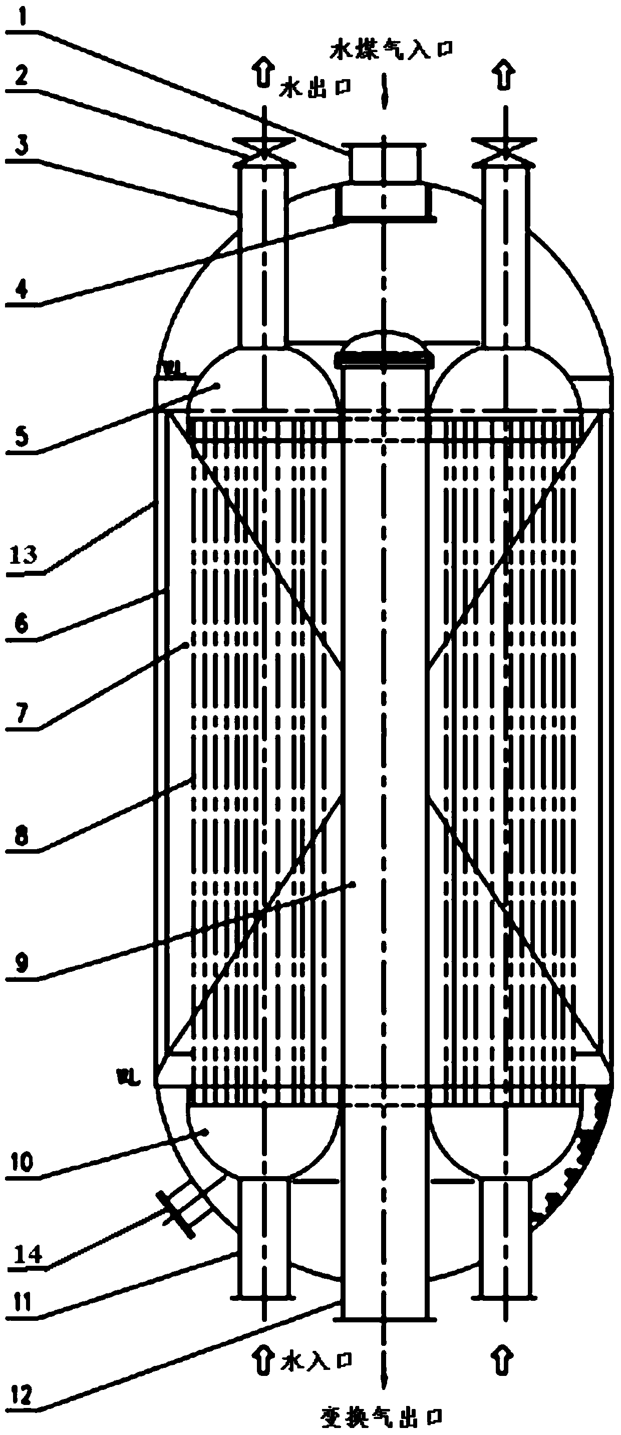
[0025] Such as figure 1 As shown, a radial flow by-product steam type isothermal shift furnace includes a ...


PUM


Abstract

The invention relates to the technical field of chemical engineering, in particular to a radial flow by-product steam isothermal shift converter. The radial by-product steam isothermal shift converter disclosed by the invention comprises a pressured furnace body, a catalyst bed, a gas distribution cylinder and a gas collector, and is characterized in that a raw material gas inlet and a water outlet are formed in the upper part of the pressured furnace body; a gas distributor is arranged in the pressured furnace body at the raw material gas inlet; a shift gas outlet and a water inlet are formed in the lower part of the pressured furnace body; the gas distribution cylinder is arranged between the inner wall of the pressured furnace body and the catalyst bed; the gas collector is arranged at the central axis of the pressured furnace body; a vertical heat extraction device is arranged in the catalyst bed, and comprises two ring-shaped tube boxes which are respectively arranged at the upper and lower positions of the catalyst red; a plurality of vertical column tubes are connected between the two ring-shaped tube boxes, and penetrate through the catalyst bed; the upper ring-shaped tube box is communicated with the water outlet; the lower ring-shaped tube box is communicated with the water inlet.

Description

technical field [0001] The invention relates to the technical field of chemical industry, in particular to a radial flow by-product steam type isothermal shift furnace. Background technique [0002] In recent years, the coal chemical technology that uses coal as raw material to produce synthetic oil, synthetic ammonia, and methanol has been vigorously developed. Among them, the typical process of CO sulfur-tolerant shift to prepare shift gas is particularly common. In the coal gasification supporting equipment, the carbon monoxide conversion device adjusts the hydrogen / carbon content of the crude gas produced by the gasification device through the conversion reaction to meet the needs of downstream products. The characteristics of gas should also take into account the requirements of follow-up devices and downstream products. The composition of crude gas produced by various gasification processes is quite different. Even for the same downstream product, the conversion proce...

Claims


Application Information

Patent Timeline
Patent Type & Authority Applications(China)
IPC IPC(8): B01J8/02C01B3/16
Inventor 赵斌义卢正滔张剑王海涛
Owner INNOVATIVE COAL CHEMICAL DESIGN INSTITUTE (SHANGHAI) CO LTD
Why Eureka
Try Eureka