Integrated liquid drop microfluidic chip

A microfluidic chip, integrated technology, applied in enzymatic/microbiology devices, biochemical instruments, biochemical equipment and methods, etc. High-sensitivity and high-throughput qualitative and quantitative detection, avoiding the formation of air bubbles, and reducing the effect of sample transfer

Inactive Publication Date: 2016-05-11
XI AN JIAOTONG UNIV
View PDF4 Cites 37 Cited by
  • Summary
  • Abstract
  • Description
  • Claims
  • Application Information

AI Technical Summary

Problems solved by technology

Firstly, the chip will inevitably cause the loss of droplets, which will affect the detection results; secondly, air bubbles are easy to be generated in the cavity of the chip, and these bubbles will continuously expand and contract during the PCR amplification process, which is extremely dangerous. may lead to the failure of the experiment
Finally, the arrangement structure of the droplets in the chip cavity is heavily dependent on the ratio of water to oil in the early stage of

Method used


Image

  • Integrated liquid drop microfluidic chip
  • Integrated liquid drop microfluidic chip
  • Integrated liquid drop microfluidic chip

Examples


Embodiment 1

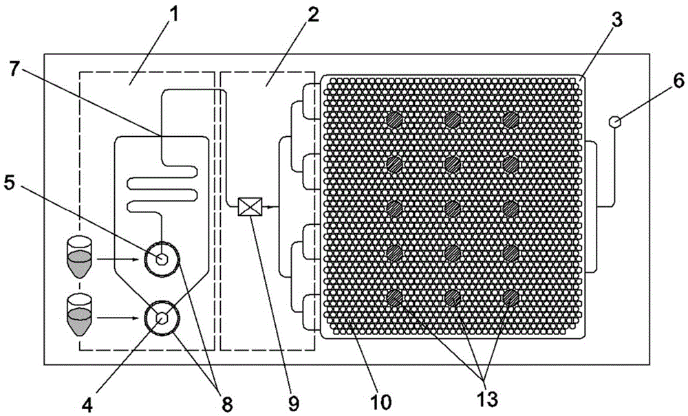
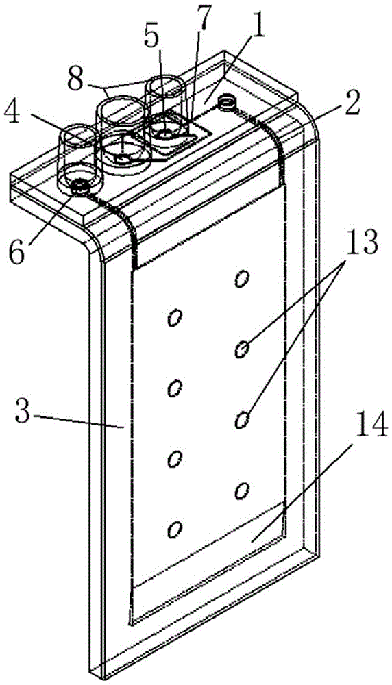
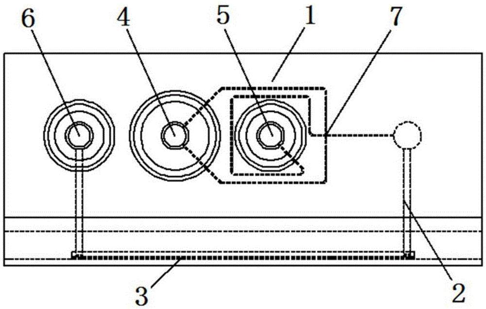
[0030] Example 1, three-dimensional single-channel droplet microfluidic chip: refer to figure 2 3(a), the three-dimensional single-channel droplet microfluidic chip includes a droplet generation structure 1, the droplet generation structure 1 communicates with the collection cavity structure 3 through the connecting channel 2, and the droplet generation structure 1 is provided with a first inlet 4. The second inlet 5 and the microchannel 7, the first inlet 4, the second inlet 5 and the microchannel 7 are connected to each other, the first inlet 4 and the second inlet 5 are respectively integrated with a liquid storage tank 8, connecting the channel 2 Consists of a channel, the outlet of the micro flow channel 7 is connected to the inlet of the collection chamber structure 3 through the connecting channel 2, and the collection chamber structure 3 is provided with an exhaust outlet 6; referring to Fig. 3(b) and Fig. 3(c), the collection The cavity structure 3 includes two oppos...

Embodiment 2

[0033] Example 2, planar multi-channel droplet microfluidic chip: refer to Figure 4 As shown in Figure 5, the planar multi-channel droplet microfluidic chip contains a parallel structure of 4 channels, which are distributed in four radial directions of the disc-shaped chip, and the angle between each other is 90°. The chip of each channel The structures all include a droplet generating structure 1, a connecting channel 2, and a collecting cavity structure 3. The droplet generating structure 1 communicates with the collecting cavity structure 3 through the connecting channel 2. The droplet generating structure 1 includes a first inlet 4, a second The inlet 5 and the microchannel 7 are respectively integrated with a liquid storage tank 8 at the first inlet 4 and the second inlet 5, and the connecting channel 2 is connected to the collection cavity structure 3 by a parallel flow path divided into two and divided into four, It is possible to keep the emulsion flowing synchronousl...


PUM


Abstract

An integrated liquid drop microfluidic chip comprises one or more liquid drop generation structures, every liquid drop generation structure is connected with a corresponding collection cavity structure through a corresponding connection channel, a water phase reagent and an oil phase reagent respectively go through the one or more liquid drop generation structures to generate liquid drops with uniform dimension, an emulsion including the liquid drops goes through the connection channel and directly or indirectly enters the collection cavity structure, and is adaptively arranged to form a regular liquid drop array in the collection cavity structure, the liquid drop array undergoes a biochemical reaction under constant temperature control or temperature circulation control in an air heating refrigeration or Peltier semiconductor heating refrigeration mode, and real time monitoring or timed optical detection is also carried out. The integrated liquid drop microfluidic chip reduces the sample transfer process, can be conveniently integrated with a thermometric module and an optical detection module, greatly improves the reaction and detection speed, and also simplifies the complex degree of a whole apparatus system.

Description

technical field [0001] The invention belongs to the technical field of biochemical microfluidics, and in particular relates to an integrated droplet microfluidics chip. Background technique [0002] At present, biochemical analysis and detection based on droplet microfluidic technology has been fully applied and developed, such as QX200 TM and Raindrop TM Digital PCR system, these two systems have greatly improved the detection sensitivity, accuracy and measurable concentration dynamic range, but they still cannot fully meet the needs of biochemical detection in practical applications. On the one hand, these two systems have high requirements for peripheral control components, which leads to increased system complexity and difficulty in reducing system costs; It is often necessary to transfer between different instruments, which makes the degree of automation and integration of the system not high. In addition, the amplification reaction and flow detection of the system t...

Claims


Application Information

Patent Timeline
IPC IPC(8): C12M1/38C12M1/34C12M1/00
CPCB01L3/5027B01L2300/18B01L2200/027
Inventor 彭年才赵书豪张增明
Owner XI AN JIAOTONG UNIV
Why Eureka
Try Eureka