Biomass pyrolysis gasification method

A technology for pyrolysis, gasification and biomass, which is applied in the manufacture of combustible gas and petroleum industry. , Improve the heating effect and shorten the conveying distance

Active Publication Date: 2016-05-18
SINOPEC DALIAN RES INST OF PETROLEUM & PETROCHEMICALS CO LTD +1
View PDF8 Cites 13 Cited by
  • Summary
  • Abstract
  • Description
  • Claims
  • Application Information

AI Technical Summary

Problems solved by technology

However, this technology also has obvious disadvantages: first, the raw material must be ground into submillimeter particles, and the biomass raw material is difficult to grind; second, it needs to consume more oxygen to generate high temperature, resulting in product gas H 2 / CO ratio is not high, energy consumption and carbon emissions are relatively high
[0006] CN102874750A discloses a method for pyrolysis and gasification of biomass and coke under a microwave field. The pyrolysis gasification rate is greater than 80%, and the hydrogen content in the gas product can reach 70%, but it cannot be completely removed by using a simple water cooling system. Tar, and there is a problem of recovery and recycling using zinc chloride as a catalyst
However, this method uses fluidized bed gasification, and the gas flow rate is fast, and it is easy to carry a large amount of particulate matter through the carbon layer, which requires subsequent deashing and impurity removal treatment.

Method used


Image

  • Biomass pyrolysis gasification method

Examples


Embodiment 1

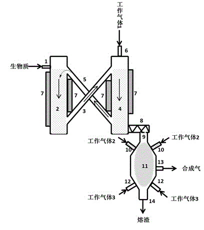
[0038] The biomass raw material with a size of 20mm enters the microwave pyrolysis reaction section 2 through the feed port 1, and at the same time starts the screw propeller 3 to send part of the biomass raw material to the microwave directional gasification section 4. When the raw material fills up to the microwave generator 7 irradiation Stop feeding and close the screw propeller 3 within the range, then turn on the microwave generator 7, and set the microwave pyrolysis reaction section 3 power 3 × 10 5 W / m 3 and microwave directional gasification section 4 power 4×10 5 W / m 3 . When the temperatures of the microwave pyrolysis reaction section 2 and the microwave directional gasification section 4 reach 600°C and 800°C respectively, the biomass raw material (10kg / h) is re-introduced and the screw propeller 3 and the screw feeder 5 are started to control the flow from the screw Bio-coke returned by feeder 5 (specific surface area 686m 2 / g, pore volume 0.21cm 3 / g) The m...


PUM

PropertyMeasurementUnit
specific surface areaaaaaaaaaaa
sizeaaaaaaaaaa

Abstract

The invention discloses a biomass pyrolysis gasification method which includes the following steps: 1) feeding a biomass raw material into a microwave pyrolysis reaction section to perform pyrolysis under microwave to generate gas, tar and semicoke as pyrolysis products; 2) respectively feeding the pyrolysis products and a first working gas into a microwave oriented gasification section to perform a gasification reaction to obtain a gasification product; 3) in the gasification product, separating gasified semicoke into two parts, wherein one part is spirally transported to the upper part of a microwave pyrolysis reaction section from the bottom of the microwave oriented gasification section so that this part of semicoke is mixed with the biomass raw material to perform microwave pyrolysis, and the other part of the semicoke is spirally transported to a plasma reaction section with a gas-phase volatile component in the gasification product; 4) performing a plasma gasification reaction to the material fed into the plasma reaction section to obtain high-quality synthetic gas which then is discharged out from a gas outlet while solid residues are discharged from the bottom of the plasma reaction section. The method is high in biomass gasification rate and carbon conversion rate. The synthetic gas is high in quality, can satisfy demand on synthetic liquid fuels and has excellent application prospect.

Description

technical field [0001] The invention belongs to the field of biofuels, and in particular relates to a biomass pyrolysis gasification method. Background technique [0002] Among many biofuel technologies, biomass indirect liquefaction has the characteristics of clean and environmentally friendly process, high product purity (oxygen content <1%, almost free of S, N and other impurities), and is a promising technical route. Biomass indirect liquefaction technology includes two stages of biomass gasification and Fischer-Tropsch synthesis, among which obtaining high-quality synthesis gas through appropriate biomass gasification technology is the key to this technology. The traditional fixed bed has consistent raw material requirements, poor heat transfer effect, and short residence time in the fluidized bed, all of which lead to a low overall carbon conversion rate, and the gasification temperature of the fixed bed or fluidized bed is generally <1000°C. The presence of tar...

Claims


Application Information

Patent Timeline
Patent Type & Authority Applications(China)
IPC IPC(8): C10J3/18C10J3/72
Inventor 王鑫刘继华张忠清
Owner SINOPEC DALIAN RES INST OF PETROLEUM & PETROCHEMICALS CO LTD
Why Eureka
Try Eureka