Rapid thin layer deep analysis method based on laser sputtering ionization

An analysis method and laser sputtering technology, which are applied in the direction of material analysis, material analysis, and measurement devices by electromagnetic means, which can solve the problem of time-consuming SIMS analysis, serious matrix effects, powerlessness in non-metal analysis, and limitation of thin-layer industrial development, etc. problems, to achieve the effect of reducing matrix effects, reducing sample damage, and relaxing the requirements of sample shape and size

Inactive Publication Date: 2014-04-16
SHENZHEN ENTRY EXIT INSPECTION & QUARANTINE BUREAU INDAL PROD INSPECTION TECH CENT
View PDF2 Cites 0 Cited by
  • Summary
  • Abstract
  • Description
  • Claims
  • Application Information

AI Technical Summary

Problems solved by technology

[0003] At present, the depth analysis techniques applied to thin layers mainly fall into two categories: spectroscopy and mass spectrometry. Among them, spectral techniques represent X-ray fluorescence spectroscopy (XRF), glow discharge spectroscopy (GD-OES), and laser-induced breakdown spectroscopy. (LIBS), but these techniques have serious spectral interference, poor sensitivity and detection limit
The mass spectrometry technologies are represented by secondary ion mass spectrometry (SIMS), glow discharge mass spectrometry (GD-MS), and laser sputtering inductively coupled mass spectrometry (LA-ICPMS). Among them, LA-ICPMS and GDMS can detect most metals elements, but is impotent for non-metallic analysis due to its plasma temperature limitation
However, SIMS has time-consuming analysis and serious matrix effects.
Therefore, various deficiencies in the current thin-layer analysis technology greatly limit the development of thin-layer industry.
[0004] In summary, the existing thin-layer analysis methods have the disadvantages of serious matrix effects, poor lateral resolution, serious spectral line interference, low sensitivity, and time-consuming analysis.

Method used


Image

  • Rapid thin layer deep analysis method based on laser sputtering ionization
  • Rapid thin layer deep analysis method based on laser sputtering ionization
  • Rapid thin layer deep analysis method based on laser sputtering ionization

Examples


Embodiment 1

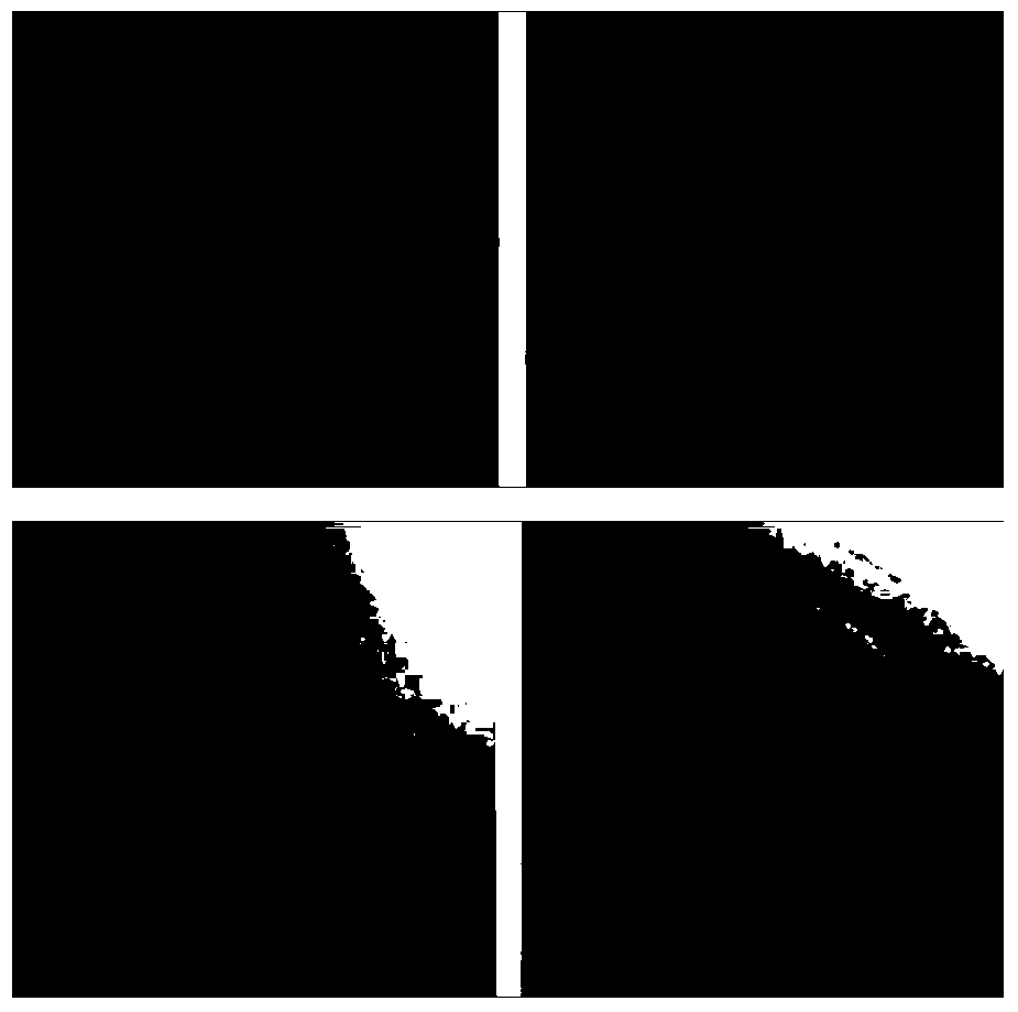
[0040] see figure 2 , discloses the metallographic microscope images of the crater after the nanosecond laser and the femtosecond laser act on the multilayer sample of the copper substrate respectively, in which (a) nanosecond laser sputtering 2 times, (b) nanosecond laser sputtering 10 times, (c ) 8 times of femtosecond laser sputtering and (d) 40 times of femtosecond laser sputtering. Among them, the nanosecond laser power is 9.0×10⁹W / cm2, and the femtosecond laser is 4.4×10¹²W / cm2. It can be seen from the figure that nanosecond laser sputtering has obvious melting, while femtosecond laser sputtering has no melting phenomenon and is very uniform. So femtosecond laser is more suitable for thin layer analysis.

Embodiment 2

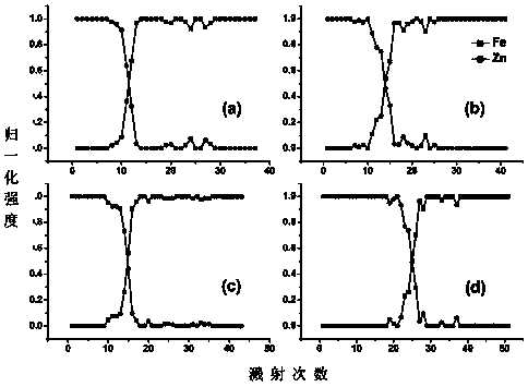
[0042] see image 3 , discloses the depth analysis diagrams of Zn layers at different depths by nanosecond laser ionization vertical time-of-flight mass spectrometry, wherein the thicknesses of Zn are 11.4, 15.5, 17.1, and 28.6 μm, respectively. from figure 2 Using the method of the present invention to analyze single-coated thin-layer samples can obtain obvious steps between the coating and the substrate, thus illustrating that the invention is suitable for single-coated sample analysis.

[0043] Further, at Figure 4 right image 3 The calibration curves of the thickness of the coating and the number of drilling pulses in the four different galvanized iron samples, the calibration curve shows that the number of laser drilling pulses increases linearly with the increase of the coating thickness, which shows that the laser sputtering rate is relatively Uniform, the coating thickness can be converted by the number of pulses.

Embodiment 3

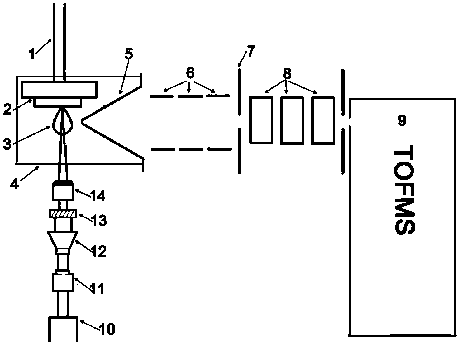
[0045] See Figure 5, which compares femtosecond and nanosecond laser ionization vertical time-of-flight mass spectrometry and analyzes the spectra obtained by different material multilayer conductor coating conductor substrates, specifically: Rh160nm / Au20nm / Pd1100nm three-layer Cu plating. It can be seen from the results that a nanosecond laser is used in Figure 5(a), and a femtosecond laser is used in Figure 5(b). It can be seen from Fig. 5(a) that due to the high sputtering rate of the nanosecond laser, the signals of the first three layers all appear after the first laser action. Therefore, nanosecond pulsed lasers cannot analyze the first three coating layers. While in Fig. 5(b) the femtosecond laser can realize the analysis of the first three layers, because the depth resolution of the femtosecond laser is higher.

[0046] Further, taking Pd as an example to calculate, it can be concluded that the nanosecond laser ionization vertical time-of-flight mass spectrometry can ...


PUM

PropertyMeasurementUnit
diameteraaaaaaaaaa
wavelengthaaaaaaaaaa

Abstract

The invention relates to a rapid thin layer deep analysis method based on laser sputtering ionization and builds a laser sputtering ionization vertical flight time mass spectrum device. The device comprises a laser optical part and a flight time mass spectrum part, wherein the optical part comprises a laser, an attenuator, a beam expander, a diaphragm and a focusing lens, the flight time mass spectrum part comprises a sample introduction probe with a two-dimension mobile platform fixed at the front end, the two-dimension mobile platform stretches into an ion source chamber, inert gases are filled into the ion source chamber, a sampling cone is arranged on one side surface of the ion source chamber, an ion lens system and a flight time mass spectrometer are sequentially arranged behind the sampling cone for detection, the spectrogram of laser action every time is made by the flight time mass spectrometer, the drilling pulse count of the laser is determined from the spectrogram, and the thickness of a clad layer is obtained. According to the method and the device, the damage to a sample is reduced, the requirements on the shape and size of the sample are broadened, the matrix effect is reduced and high sensitivity, low detection limit and high analysis speed are achieved.

Description

technical field [0001] The present application relates to a thin-layer analysis method, in particular, to a method for rapid depth analysis of a thin layer using laser sputtering ionization. Background technique [0002] With the development of material science and surface science, the application of plating and coating has become more and more common. Using surface treatment technology to cover one or more layers of substances on the surface of the product can not only make the product have a beautiful appearance, but also improve its protective performance. The application of this technology has been extended from daily life to scientific precision instrument development and other fields. In most cases, the properties of thin-layer materials are closely related to the thickness, composition and depth distribution of coating elements. Therefore, the in-depth analysis of thin layers is very important. [0003] At present, the depth analysis techniques applied to thin laye...

Claims


Application Information

Patent Timeline
Patent Type & Authority Applications(China)
IPC IPC(8): G01N27/64
Inventor 余淑媛杭纬李彬吴透明刘志红冯均利任聪李勇王嘉莉宋保靓吴景武刘冬
Owner SHENZHEN ENTRY EXIT INSPECTION & QUARANTINE BUREAU INDAL PROD INSPECTION TECH CENT
Why Eureka
Try Eureka