

Active-passive upper limb rehabilitation training exoskeleton
A rehabilitation training and exoskeleton technology, applied in passive exercise equipment, sports accessories, elastic resistance devices, etc., can solve the problems of low energy utilization, no indirection and aesthetics, and complex structure.
- Summary
- Abstract
- Description
- Claims
- Application Information
AI Technical Summary
Problems solved by technology
Method used
Image

Examples
specific Embodiment approach 1
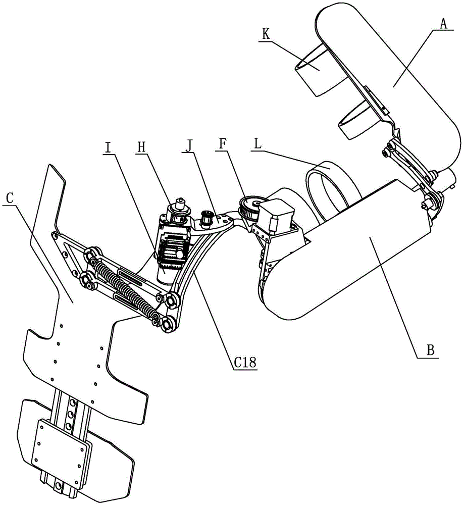
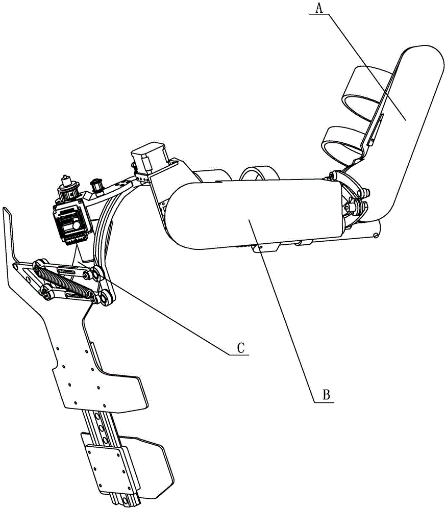
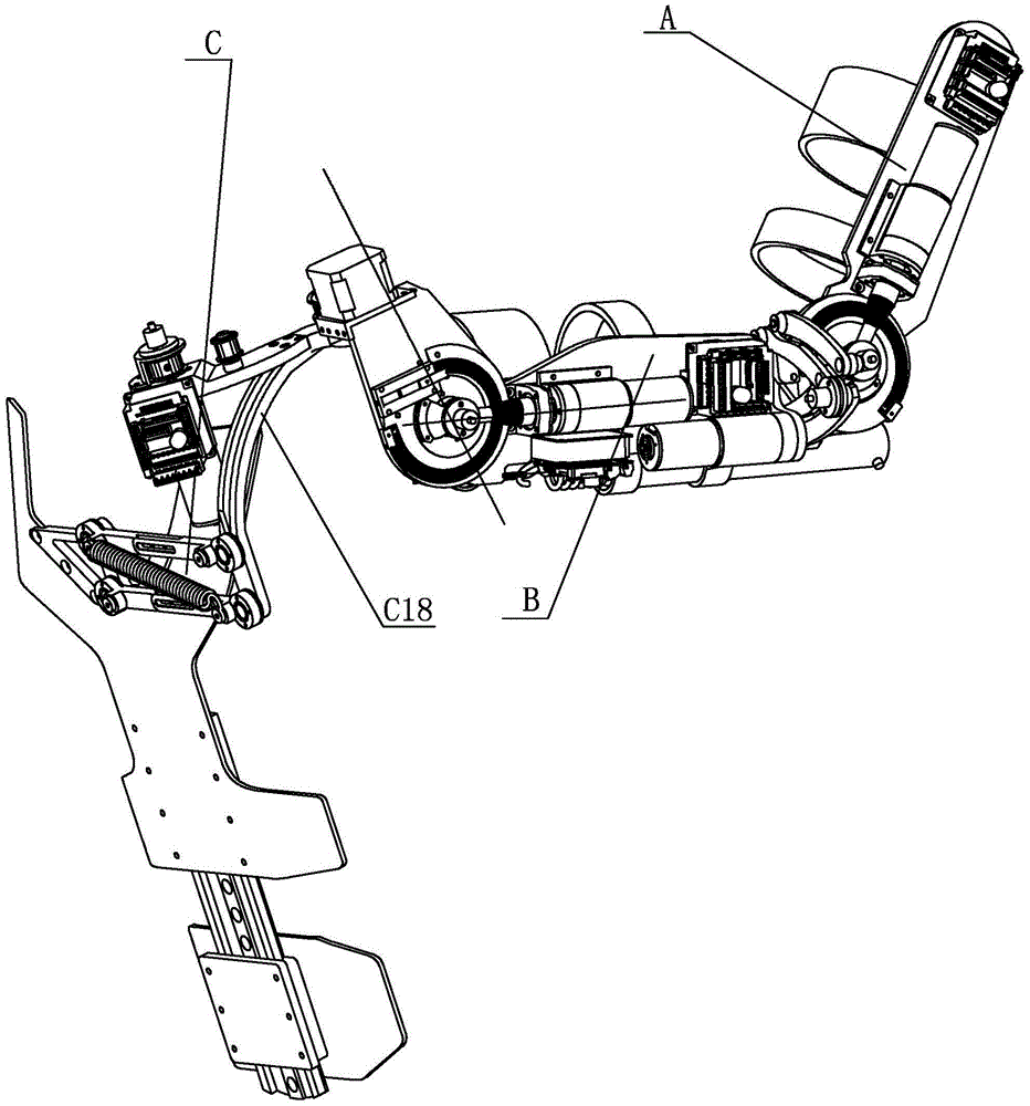
[0029] Specific implementation mode one: combine Figure 1 to Figure 12 Describe this embodiment, this embodiment includes forearm A, big arm B, back C, external rotation shaft D, bearing E, driving pulley F, synchronous belt G, driven pulley H, back drive motor I, The back drive motor seat J, the forearm binding mechanism K, the big arm binding mechanism L, the back drive motor driver P and the back drive motor driver bracket Q,
[0030] See Figure 11, the elbow joint connection seat B45 on the big arm B is fixedly connected with the elbow joint output wheel A4 on the forearm A, one end of the external rotation axis D is hinged in the horizontal frame B1-2 of the shoulder joint skeleton B1, and the external rotation axis D The other end is connected to the inner ring of the bearing E, the shaft end retaining ring M fixes the axial position of the external rotation shaft D, the driving pulley F is fixed on the external rotation shaft D, and one end of the timing belt G is sl...
specific Embodiment approach 2
[0031] Specific implementation mode two: combination Figure 4 and Figure 5 Describe this embodiment, the forearm A of this embodiment includes forearm driver A1, forearm drive motor A2, forearm bearing seat A3, elbow joint output wheel A4, forearm steel wire pretensioning mechanism A5, forearm chute A7, Exoskeleton base plate A8, forearm drive motor base A9, forearm reducer A10, elbow joint input shaft A11, forearm wire rope fixing device A13, elbow joint rotation axis A16 and forearm wire rope A17, and forearm driver A1 is fixedly connected to the exoskeleton On one end surface of the substrate A8, the forearm binding mechanism K is hinged on the other end surface of the exoskeleton substrate A8, the forearm driver A1 is fixedly connected to the exoskeleton substrate A8, and the forearm driver A1 is electrically connected to the forearm drive motor A2 , the forearm drive motor A2 is connected with the forearm reducer A10, the forearm reducer A10 is fixedly connected with t...
specific Embodiment approach 3
[0032] Specific implementation mode three: combination Figure 4 and Figure 5 Describe this embodiment. The difference between this embodiment and the second embodiment is that the forearm A also includes the forearm encoder bracket A6 and the forearm encoder A12, and the forearm encoder bracket A6 is fixed to the elbow joint output wheel A4. The forearm encoder A12 is fixedly connected to the forearm encoder bracket A6. Forearm encoder A12 is used to detect the rotation angle of the elbow joint. The degree of freedom here is the rotational degree of freedom of the elbow joint, which is driven by the forearm drive motor A2. Other components and connections are the same as those in the second embodiment.
PUM
 Abstract
Description
Claims
Application Information