An integrated treatment system for chemical nickel waste liquid
A treatment system, chemical nickel technology, applied in the direction of metallurgical wastewater treatment, chemical instruments and methods, water/sewage multi-stage treatment, etc., can solve the problems of non-removable, pollution and secondary pollution, etc.
- Summary
- Abstract
- Description
- Claims
- Application Information
AI Technical Summary
Problems solved by technology
Method used
Image
Examples
Embodiment 1
[0039] Embodiment 1: An integrated treatment system for chemical nickel waste liquid
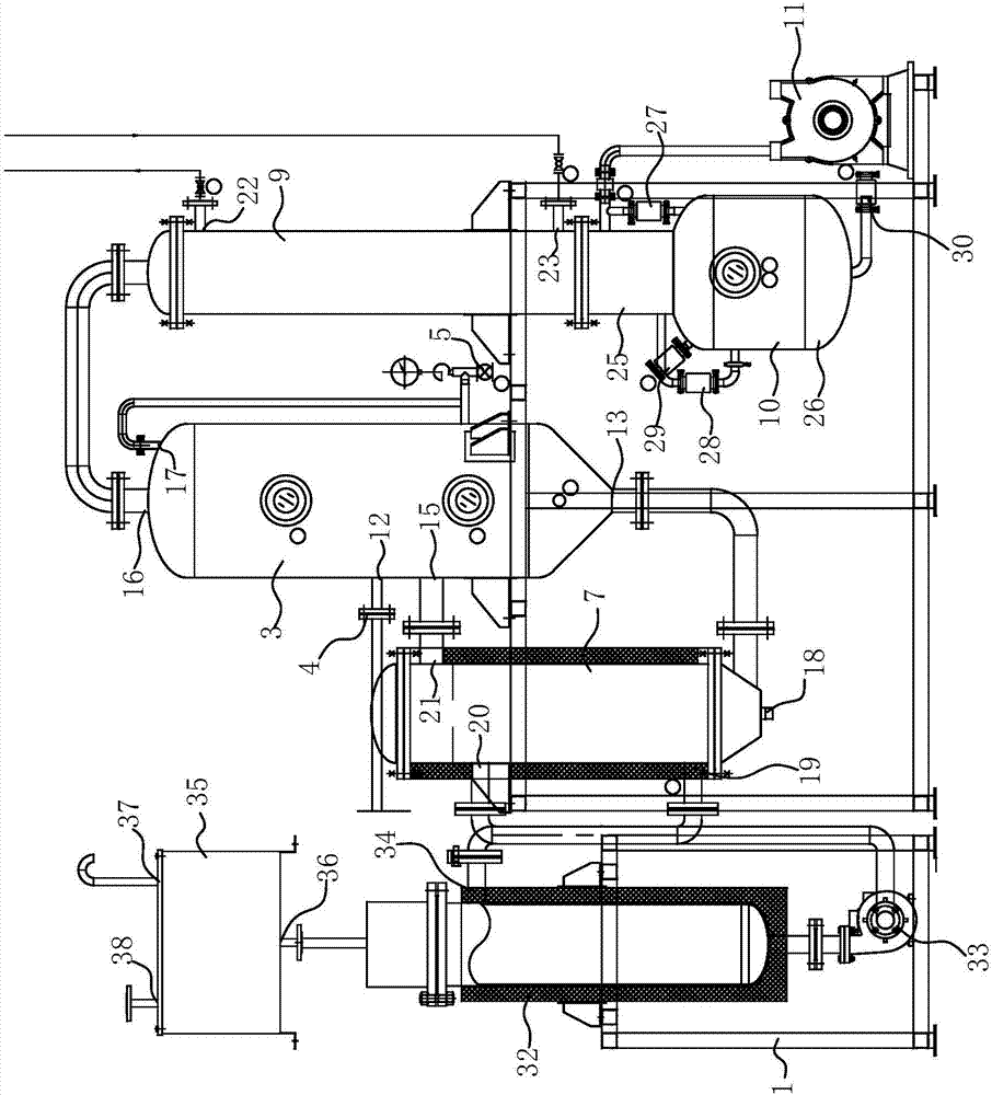
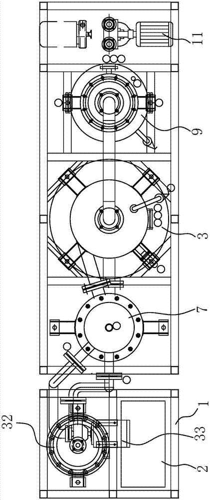
[0040] See attached figure 1 And attached figure 2 As shown, the chemical nickel waste liquid integrated treatment system can separate the chemical nickel waste liquid from solid to liquid. The chemical nickel waste liquid integrated treatment system includes an outer support frame 1, evaporation equipment, heat transfer oil circulation equipment, electric control box and automatic control unit; the evaporation equipment includes a vapor-liquid separator 3, a feed valve 4, a vent valve 5, one or two heating chambers 7, a concentrated liquid discharge valve, a condenser 9, a water storage tank 10, and a vacuum pump 11; the steam Liquid separator 3 is a container for separating steam and feed liquid, and the bottom of vapor-liquid separator 3 is provided with a material inlet 12, and material inlet 12 is connected with described feed valve 4 by pipeline, and the vapor-liquid separator 3 The...
Embodiment 2
[0047] Embodiment 2: An integrated treatment system for chemical nickel waste liquid
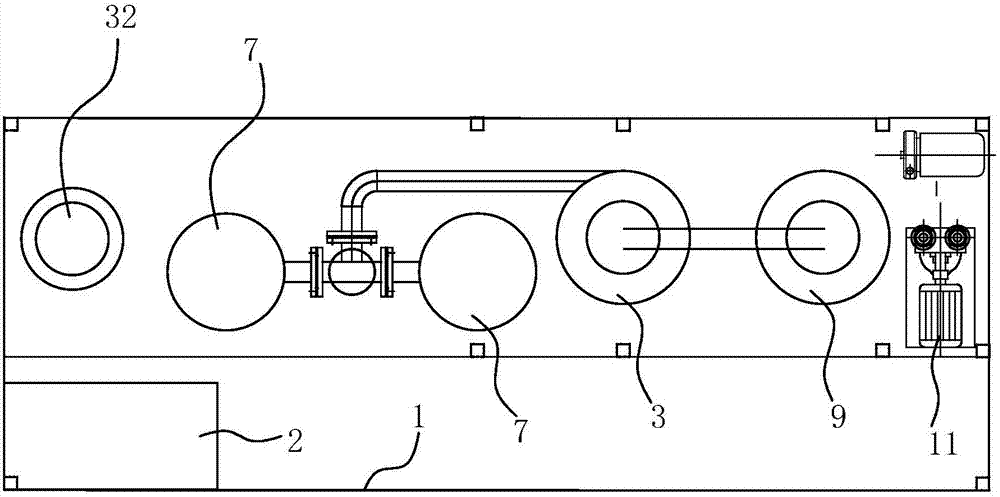
[0048] On the basis of the structural structure of the chemical nickel waste liquid integrated treatment system in Embodiment 1, the number of the heating chambers 7 is two, and the heating and heating tank 32 of the heat transfer oil circulation equipment is respectively connected with the two heating chambers through parallel pipelines. The heat transfer medium inlet 19 of the chamber 7 is communicated, and the steam inlet 15 on the vapor-liquid separator 3 is respectively communicated with the second steam outlets 21 of the two heating chambers 7 through parallel pipelines, see attached figure 2 As shown, the two heating chambers 7 can be respectively defined as the first heating chamber and the second heating chamber, and the heat transfer oil circulation equipment, the first heating chamber, and the second heating chamber are located on the outer support frame 1 in sequence from left to...
PUM
 Abstract
Description
Claims
Application Information
 - R&D
- Intellectual Property
- Life Sciences
- Materials
- Tech Scout
- Unparalleled Data Quality
- Higher Quality Content
- 60% Fewer Hallucinations
Browse by: Latest US Patents, China's latest patents, Technical Efficacy Thesaurus, Application Domain, Technology Topic, Popular Technical Reports.
© 2025 PatSnap. All rights reserved.Legal|Privacy policy|Modern Slavery Act Transparency Statement|Sitemap|About US| Contact US: help@patsnap.com


