

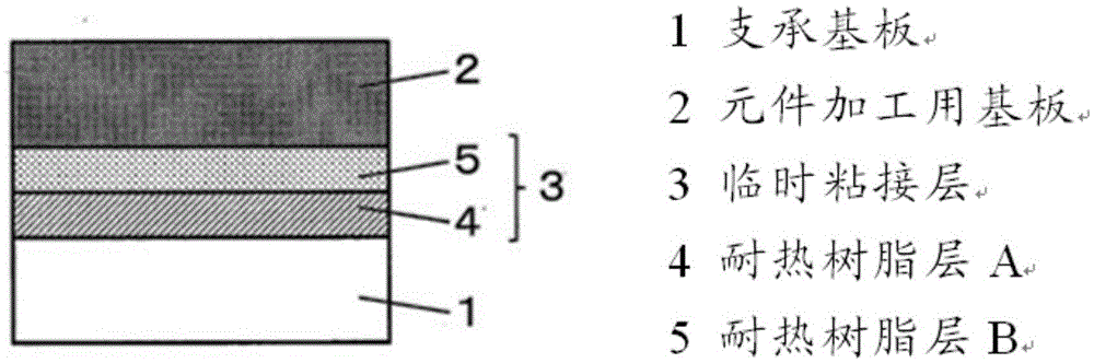
Element-processing layered structure, method for manufacturing element-processing layered structure, and method for manufacturing thin element using same
A manufacturing method and laminated body technology, applied in semiconductor/solid-state device manufacturing, electrical components, chemical instruments and methods, etc., can solve problems such as reduced adhesion, melting of solder bumps, inability to peel off, etc., and achieve the effect of improving productivity
- Summary
- Abstract
- Description
- Claims
- Application Information
AI Technical Summary
Problems solved by technology
Method used
Image

Examples
Embodiment
[0083] The following examples are given to illustrate the present invention, but the present invention is not limited by these examples. Evaluation methods for glass transition temperature, weight loss rate, and adhesive force will be described.
[0084] (1) Determination of glass transition temperature
[0085] Using a bar coater, apply the heat-resistant resin solutions (B1 to B9, A1 to A6) described in Production Examples 1 to 15 below to a thickness of 20 μm on the glossy surface of an electrodeposited copper foil with a thickness of 18 μm , and then dried at 80° C. for 10 minutes, dried at 150° C. for 10 minutes, and then heat-treated at 250° C. for 10 minutes in a nitrogen atmosphere to convert to polyimide and obtain resin-laminated copper foil. Next, the entire surface of the copper foil in the obtained resin-laminated copper foil was etched with a ferric chloride solution to obtain a single film of heat-resistant resin.
[0086] A single film of about 10 mg of the o...
manufacture example 1
[0119] Production example 1 (polymerization of heat-resistant resin B solution)
[0120]In the reaction kettle that has thermometer, dry nitrogen inlet, utilizes the heating · cooling device of warm water · cooling water, and stirring device, charge 75.7g (0.7mol) PDA, 60.1g (0.3 mol) DAE, after dissolving, add 176.5g (0.6mol) BPDA, 87.2g (0.4mol) PMDA, react at room temperature for 1 hour, then react at 60°C for 5 hours to obtain a 15% by weight polyamic acid resin solution (B-1).
manufacture example 2~7
[0121] Production examples 2 to 7 (polymerization of heat-resistant resin B solution)
[0122] According to changing the kind and charging amount of acid dianhydride and diamine as shown in Table 1, except that, carry out the operation similar to Manufacturing Example 1, obtain the polyamic acid resin solution of 15% by weight (B-2~ 7).
PUM
| Property | Measurement | Unit |
|---|---|---|
| Thickness | aaaaa | aaaaa |
Abstract
Description
Claims
Application Information