A method and equipment for continuous in-situ catalytic cracking of biomass raw materials for cogeneration of gas and carbon

A biomass raw material and in-situ catalysis technology, which is applied in the direction of biofuel, special carbonization, indirect heating carbonization, etc., can solve the problems of low gas active components, low quality of biomass charcoal, and low utilization efficiency of biomass energy. Achieve the effects of improving utilization efficiency, wide application, and improving effective gas components

Inactive Publication Date: 2019-05-24
HUAZHONG NORMAL UNIV +1
View PDF10 Cites 0 Cited by
  • Summary
  • Abstract
  • Description
  • Claims
  • Application Information

AI Technical Summary

Problems solved by technology

[0005] The purpose of the present invention is to solve the shortcomings of the current biomass gasification process, such as low gas effective components, the existence of tar affecting the continuous and stable operation of the process, low quality of biomass charcoal, and low utilization efficiency of biomass energy, etc., and develop a continuous A method and equipment for externally heated biomass in-situ catalytic cracking gas and carbon co-production. In this method, a cracking reforming catalyst with catalytic cracking activity and biomass raw materials are evenly added to a moving bed reactor for gasification, and the The biomass gasification process is integrated with the external combustion heating process, and the external fuel combustion provides heat energy for the catalytic cracking of the tar produced in the anaerobic pyrolysis gasification and gasification process of the biomass, because the biomass is isolated Pyrolysis and gasification under anaerobic conditions in the external environment. The tar produced during the gasification process can be catalytically cracked into small molecular effective gas components in situ under the action of the cracking and reforming catalyst. At the same time, CO can also be catalytically reformed. The transformation reaction takes place to generate H 2 , so that the H in the effective components of the gas produced 2 The content has been significantly increased

Method used


Image

  • A method and equipment for continuous in-situ catalytic cracking of biomass raw materials for cogeneration of gas and carbon
  • A method and equipment for continuous in-situ catalytic cracking of biomass raw materials for cogeneration of gas and carbon
  • A method and equipment for continuous in-situ catalytic cracking of biomass raw materials for cogeneration of gas and carbon

Examples


Embodiment 1

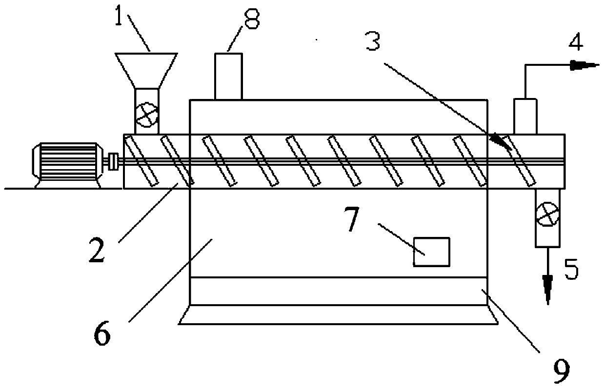
[0031] Such as figure 1 As shown, the continuous external heating biomass in-situ catalytic cracking gas and carbon co-production equipment includes moving bed reactor 2 and external combustion reactor 6 for biomass in-situ catalytic cracking, and the moving bed reactor is located outside In the combustion reactor, there is a silo 1 above one end of the moving bed reactor, a biomass pyrolysis gas outlet 4 above the other end, and a biomass charcoal and cracking catalyst outlet 5 below. There is a rotating lifting plate 3, and the rotating lifting plate continuously sends the mixture of biomass raw material and cracking catalyst fed through the silo into the middle of the moving bed reactor under the action of external force to carry out the pyrolysis and cracking reforming process of biomass charcoal. The external combustion reactor is provided with a fuel inlet 7 and an air chamber 9 for supplying fuel combustion aids, and the upper part of the external combustion reactor is ...

Embodiment 2

[0036] The chaff biomass raw material and the cracking reforming catalyst are mixed according to the mass ratio of 7.5:0.5, and then enter the mobile reactor 2 from the silo 1, and the biomass for complete combustion is sent from the entrance 7 of the external combustion reactor 6. into the external combustion reactor, complete combustion under the action of the air provided by the air chamber 9, while controlling the air-fuel ratio, the combustion reaction temperature is controlled within the temperature range of 650-800 °C, and the flue gas generated after combustion is discharged from the 8, due to The moving bed reactor is located in the external combustion reactor 6. Biomass fuel etc. are burned in the combustion reactor 6, and the heat generated by the combustion is supplied to the biomass in the moving bed reactor 2 through heat radiation, convection and heat conduction. The heat required for the pyrolysis of substances and the accompanying in-situ catalytic cracking of ...


PUM

PropertyMeasurementUnit
particle diameteraaaaaaaaaa
specific surface areaaaaaaaaaaa

Abstract

The invention discloses a method and equipment for continuous co-production of gas and charcoal through biomass material in-situ catalytic cracking. The method is characterized in that a cracking and reforming catalyst and biomass materials are mixed and then fed into a moving bed reactor; biomass is subjected to anaerobic pyrolysis to produce biomass gas under the condition that an external reactor provides a heat source; tar produced during the biomass gasification process is subjected to in-situ catalytic cracking to produce small molecular gas under the action of a catalyst; in addition, part of CO is further cracked and reformed into H2; the catalyst subjected to catalytic action and biomass charcoal are discharged from the moving bed reactor; the catalyst and the biomass charcoal are obtained after magnetic separation; the catalyst is reused, and the biomass charcoal serves as the carrier of the catalyst, an adsorbent or a soil conditioner to be used. The method and equipment solve the disadvantages that during the current biomass gasification process, the content of effective gas composition in gas is low, the existence of jar affects continuous and stable operation of the process, the biomass charcoal quality is low, and the utilization efficiency of biomass energy is low.

Description

technical field [0001] The invention belongs to the technical field of biomass energy, and in particular relates to a method and equipment for continuous in-situ catalytic cracking of biomass raw materials and co-production of gas and charcoal. Background technique [0002] Biomass raw material refers to a kind of energy that converts solar energy into chemical energy through photosynthesis and stores it in plants. 2 The net emissions are zero, which has attracted widespread attention. [0003] At present, the large-scale utilization of biomass energy is mostly used in the form of air gasification, due to the dilution of nitrogen in the air (N 2 The volume percentage concentration in the outlet gas is about 60%), which leads to the low calorific value of the gas produced by biomass gasification, and the volume ratio concentration of the effective gas is not high (H 2 : about 10%; CO: about 18%), which limits its utilization. In addition, the mass percentage of carbon resid...

Claims


Application Information

Patent Timeline
Patent Type & Authority Patents(China)
IPC IPC(8): C10B53/02C10B47/20C10B57/18
CPCC10B47/20C10B53/02C10B57/18Y02E50/10
Inventor 吴正舜田江吴海波彭乔姜晓敏张如月汪俊时
Owner HUAZHONG NORMAL UNIV
Why Eureka
Try Eureka