Two-stage heavy oil slurry-bed reactor hydrogenation equipment and method

A technology of hydrogenation equipment and slurry bed, which is applied in the field of heavy oil hydrogenation equipment, can solve problems such as hydrogenation catalyst poisoning, catalyst pore blockage, and reactor working condition deterioration, and achieve high conversion rate of heavy oil and increase compatibility , Improve the effect of hydrogenation conversion rate

Inactive Publication Date: 2016-06-01
CHINA PETROLEUM & CHEM CORP +1
View PDF3 Cites 2 Cited by
  • Summary
  • Abstract
  • Description
  • Claims
  • Application Information

AI Technical Summary

Problems solved by technology

At present, the most commonly used in the hydrogenation process is the downflow fixed bed reactor, that is, the trickle bed reactor, but heavy oil products such as residual oil and coal liquefied oil are prone to poisoning of the hydrogenation catalyst or catalyst pores due to high impurity content. Blockage and rapid deactivation, and impurities may block the bed layer, causing a rapid increase in pressure drop, resulting in poor reactor conditions, or even failure to operate normally

Method used


Image

  • Two-stage heavy oil slurry-bed reactor hydrogenation equipment and method

Examples


Embodiment 1

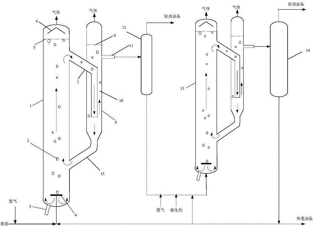
[0048] Use as attached figure 1 In the two-stage heavy oil slurry bed hydrogenation equipment shown, in the first and second slurry bed reactors, the diameter ratio of the riser to the downcomer is 2:1, and the diameter ratio of the downcomer to the upper connecting pipe is 4:1. The connecting position of the rising pipe and the descending pipe is at the interface between the upper connecting pipe and the rising pipe, 3m away from the top of the rising pipe, and 2.5m away from the bottom of the rising pipe at the interface between the lower connecting pipe and the rising pipe.

[0049] Hydrocracking catalyst preparation method: metal precursor ammonium molybdate ((NH 4 )6Mo 7 o 24 4H 2 O), nickel nitrate (Ni(NO 3 ) 2 ·6H 2 O) and vanadium oxide (V 2 o 5 ) with a mass ratio of 3.3:4.16:1, added to water, and stirred evenly. Then add acid-treated activated carbon 3.5 times the total mass of the metal precursor and 0.34 times the vulcanizing agent (sublimed sulfur) into...


PUM

PropertyMeasurementUnit
particle diameteraaaaaaaaaa

Abstract

Two-stage heavy oil slurry-bed reactor hydrogenation equipment and a method thereof are disclosed. The equipment comprises a first slurry-bed reactor, a first separating unit communicated with the first slurry-bed reactor, a second slurry-bed reactor communicated with a discharge port of the first separating unit, and a second separating unit communicated with the second slurry-bed reactor. The first and second slurry-bed reactors comprise a riser tube (1) and a downcomer (8). Upper parts and lower parts of the riser tube (1) and the downcomer (8) are respectively communicated through connecting pipes. An opening of the upper connecting pipe (7) extends into the lower part of the downcomer (8). The bottom of the riser tube (1) is provided with a raw material inlet. Tops of the riser tube (1) and the downcomer (8) are respectively provided with gas outlets. The middle upper part of the downcomer (8) is provided with a product outlet. The two-stage heavy oil slurry-bed reactor hydrogenation equipment and the method are convenient for long-term operation of the reactors, hydrogenation conversion rate of heavy oil is raised, and slurry processing of subsequent equipment is enhanced.

Description

technical field [0001] The invention relates to a heavy oil hydrogenation equipment and method, more specifically, to a heavy oil hydrogenation equipment and method using a two-stage slurry bed reactor. Background technique [0002] Hydrogenation is an important technical route for the treatment of inferior raw materials. Through hydrogenation, impurities such as metals, colloids, residual carbon, sulfur, and nitrogen in heavy oil products can be effectively removed. At present, the most commonly used in the hydrogenation process is the downflow fixed bed reactor, that is, the trickle bed reactor, but heavy oil products such as residual oil and coal liquefied oil are prone to poisoning of the hydrogenation catalyst or catalyst pores due to high impurity content. Blockage and rapid deactivation, and impurities may block the bed layer to cause a rapid increase in pressure drop, resulting in poor working conditions of the reactor, or even failure to operate normally. The react...

Claims


Application Information

Patent Timeline
Patent Type & Authority Applications(China)
IPC IPC(8): C10G67/02
Inventor 唐晓津张占柱侯栓弟朱振兴胡立峰王子军侯焕娣董明
Owner CHINA PETROLEUM & CHEM CORP
Why Eureka
Try Eureka