

Artificial intelligence sheet metal part producing system
A production system and artificial intelligence technology, applied in the direction of connecting components, manufacturing tools, metal processing, etc., can solve the problems of potential safety hazards in stamping parts, low equipment utilization, low efficiency, etc., to ensure product quality and prevent size out-of-tolerance Effect
- Summary
- Abstract
- Description
- Claims
- Application Information
AI Technical Summary
Problems solved by technology
Method used
Image

Examples
Embodiment Construction
[0045] The present invention will be further described by taking the production of sheet metal parts in two air conditioner factories as an example below in conjunction with the accompanying drawings.
[0046] The core of automated production is ordered production, that is, sequencing is the most crucial process in automated production.
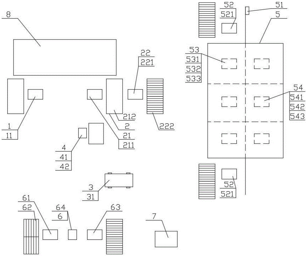
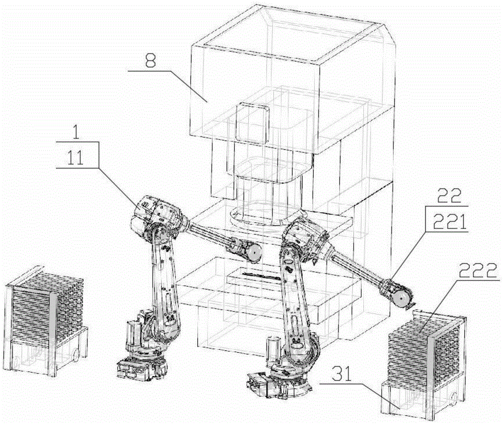
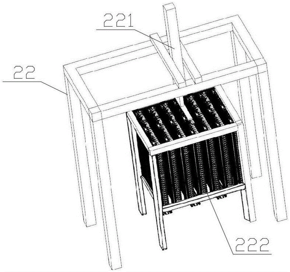
[0047] Such as figure 1 As shown, the artificial intelligence sheet metal production system includes a material supply unit 1 , an automatic code retrieval unit 2 for formed sheet metal parts, an intelligent logistics palletizing and transporting unit 3 and a centralized electronic control unit 7 .
[0048] Such as figure 2 As shown, the material supply unit 1 is arranged at the feeding end of the sheet metal processing equipment 8 such as a stamping machine, a compound machine or a forming machine, and includes an automatic feeding device 11, which can make and shape the material according to the stamping size requirements. The steel plat...
PUM
 Abstract
Description
Claims
Application Information