Smart energy-saving pumping unit and automatic control method thereof

A kind of pumping unit, intelligent technology, applied in pump control, machine/engine, mechanical equipment, etc., can solve the problems of rough balance adjustment, too light balance, poor balance effect of pumping unit, etc., to reduce the energy transmission path , the balance accuracy is improved, and the energy saving effect is remarkable.

Inactive Publication Date: 2016-06-15
北京中泰隆节能环保科技有限公司
View PDF6 Cites 10 Cited by
  • Summary
  • Abstract
  • Description
  • Claims
  • Application Information

AI Technical Summary

Problems solved by technology

Since the pumping unit is a periodic alternating load with impact, in order to ensure sufficient overload capacity during operation, the drive motor with the largest capacity is often used, and the problem of "big horse and small cart" is common, and the motor When running, it needs to be output through a multi-stage gearbox and a connecting rod mechanism, which consumes a lot of power, resulting in very low operating efficiency and power factor. Generally, the overall efficiency of the system is only 30% to 40%.
In addition, when the beam pumping unit is working, due to the unevenness of the load change at the suspension point, the balance effect of the pumping unit is poor, resulting in high wear and energy consumption and poor stability. In order to reduce the unevenness of the load, the beam pumping The type pumping unit is generally equipped with a balance device, and some pumping units are equipped with a counterweight and fixed on the crank, but the load and centrifugal force of this method are relatively large, and some pumping units are equipped with a balance device on the beam. Or balance the counterweight, adjust the balance by manually moving the position of the counterweight or manually adding or subtracting the mass of the counterweight to change the balance moment. These two balancing methods or the composite balance formed by the two still have cumbersome, time-consuming, labor-intensive, and balancing problems. Too light or too heavy balance leads to extremely limited adjustment range, poor balance accuracy and high maintenance cost. Therefore, the existing beam pumping unit cannot adapt to the dynamic change of load well, and generally relies on increasing the output of the motor. power to make up for it, which increases the energy consumption of the pumping unit, and the operating noise of the pumping unit is huge
In addition, the intelligent automation control level of the pumping unit also has lag defects. The ground and downhole conditions cannot be included in the intelligent control system in a real-time and effective manner. There are obvious limitations under the complex working conditions of oilfield production, especially the number of strokes and balance. Automatic and loss-free or low-loss adjustment cannot be achieved, and the balance accuracy is far from adapting to load changes
For example, on July 15, 2015, the publication number is CN104775792A patent application for the invention of the intelligent pumping unit. Although the intelligent pumping unit has realized the function of automatically adjusting the balance degree, it is limited by its transmission mechanism and ordinary motor, so that the The balance adjustment of the machine is rough, not precise enough, and the adjustment range is limited
At the same time, the pumping unit also has the defects of small motor power factor, long transmission chain, complex structure and large energy loss
And in the oil pumping operation in the oil field, the situation of slight jamming of the sucker rod occurs from time to time. Once the slight jamming of the sucker rod occurs, the falling speed of the sucker rod is slower than the falling speed of the donkey head, and an over-balance phenomenon will occur, which will cause the motor to The load increases sharply, the energy consumption is huge, and it may cause shutdown or motor burnout, seriously affecting oil field operations

Method used


Image

  • Smart energy-saving pumping unit and automatic control method thereof
  • Smart energy-saving pumping unit and automatic control method thereof
  • Smart energy-saving pumping unit and automatic control method thereof

Examples


Embodiment 1

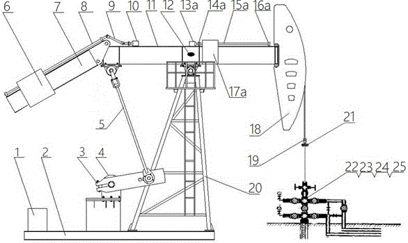
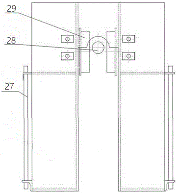
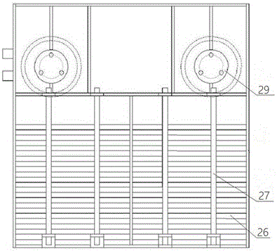
[0037] see figure 1 , figure 2 , image 3 , an intelligent energy-saving pumping unit includes a beam 11, a donkey head 18, a tail beam 7, a bracket 20, a base 2, a main motor 4, a crank 3, a connecting rod 5, a rope suspension 19, an intelligent control cabinet 1 and several The working condition sensor, the working condition sensor includes the load sensor 21 located on the rope hanger 19, the angular displacement sensor 12 located on the upper part of the connection between the beam 11 and the support 20, and the liquid level sensor 22, pressure sensor 23, flow rate sensor located on the wellhead respectively. The transmitter 24 and the temperature and humidity sensor 25 are provided with a tail beam balancing device at the tail end of the beam 11, which includes a tail beam counterweight box 6 assembled on the tail beam 7 body and a stepping motor that drives the counterweight box to move 10. The stepper motor 10 is set on the beam 11, connected with the sliding screw 8...

Embodiment 2

[0048] see Figure 5 The difference between this embodiment and Embodiment 1 is that when the beam 11 adopts a rectangular cylinder structure, the built-in balance fine-tuning device is arranged in the beam body, and the device includes the Servomotor 13b, left bearing 14b and right bearing 16b in the beam 11 body, the leading screw 15b that is parallel with swimming beam 11 is arranged between left bearing 14b and right bearing 16b, and this leading screw is connected with servomotor 13b, The lead screw 15b is equipped with a fine-tuning counterweight lead block 17b threadedly connected with it.

[0049] see Image 6 It is a control system block diagram of the present invention, and the automatic control method of the intelligent pumping unit of the present invention comprises the following steps:

[0050] (1) Startup: the power frequency power supply is introduced into the electronic control unit, and the main drive module of the electronic control unit automatically selec...


PUM


Abstract

A smart energy-saving pumping unit comprises a walking beam, a horsehead, a tail beam, a support, a base, a main motor, a crank, a connecting rod, a beam hanger, an intelligent control cabinet and a plurality of working condition sensors, wherein the main motor is a low-speed constant-torque permanent magnetic direct drive motor; a motor shaft is connected with the crank; the centrifugal end of the crank is connected with the walking beam through the connecting rod; the walking beam is provided with an external accurate adjustment balancing device or an internal accurate adjustment balancing device; the tail end of the walking beam is provided with a tail beam balancing device; an electronic control unit and a remote terminal intelligent unit are arranged in the intelligent control cabinet; the remote terminal intelligent unit is in wired connection with the electronic control unit; and the remote terminal intelligent unit is wirelessly connected with all the working condition sensors. The smart energy-saving pumping unit disclosed by the invention is high in intelligent automation degree, high in power factor, accurate in adjustment on degree of balance and good in energy-saving effect, and is capable of effectively saving energy by more than 40 percent in comparison with a traditional walking-beam pumping unit.

Description

technical field [0001] The invention belongs to the technical field of oil pumping equipment, and in particular relates to an intelligent energy-saving oil pumping unit and an automatic control method thereof. Background technique [0002] The pumping unit is the main energy-consuming equipment in the oil field. At present, most of the pumping units used in the oil field are beam pumping units. This pumping unit is driven by a common motor, and reciprocates through a multi-stage reduction box and a connecting rod and a beam. Since the pumping unit is a periodic alternating load with impact, in order to ensure sufficient overload capacity during operation, the drive motor with the largest capacity is often used, and the problem of "big horse and small cart" is common, and the motor When running, it needs to be output through a multi-stage reduction box and a linkage mechanism, which consumes a lot of power, resulting in low operating efficiency and power factor. Generally, t...

Claims


Application Information

Patent Timeline
IPC IPC(8): E21B43/00F04B47/14F04B49/06
CPCE21B43/121E21B43/127F04B47/14F04B49/065
Inventor 贾俊培戚思明李军
Owner 北京中泰隆节能环保科技有限公司
Why Eureka
Try Eureka