Direct-conversion radio frequency receiving front-end circuit device

A radio frequency receiving and front-end circuit technology, applied in electrical components, transmission systems, etc., can solve the problems of high gain requirements of the front-stage low-noise amplifier, high noise, small passive CMOS mixer gain, etc., and achieve superior gain performance. , the effect of reducing noise and improving overall performance

Active Publication Date: 2016-06-15
AEROSPACE INFORMATION
View PDF2 Cites 4 Cited by
  • Summary
  • Abstract
  • Description
  • Claims
  • Application Information

AI Technical Summary

Problems solved by technology

[0004] The shortcoming of the radio frequency receiving front end of the above-mentioned prior art direct conversion is: in the low noise amplifier, the cascaded structure of the mixer, because the gain of the passive CMOS mixer is small, the gain of the system for the front stage low noise amplifier more demanding
On the other hand, the high noise of Gilbert type active mixer, especially the flicker noise leakage of the switch pair will seriously deteriorate the receiving performance of the direct conversion system
Noise is higher in the fusion structure of LNA and mixer

Method used


Image

  • Direct-conversion radio frequency receiving front-end circuit device
  • Direct-conversion radio frequency receiving front-end circuit device
  • Direct-conversion radio frequency receiving front-end circuit device

Examples


Embodiment 1

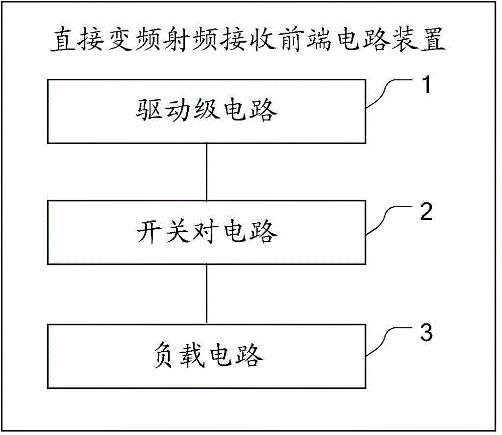
[0025] The direct conversion radio frequency receiving front-end circuit device proposed by the embodiment of the present invention can be regarded as the structural integration of the source degenerated low noise amplifier and the active mixer. The module structure diagram of the device is as follows figure 1 As shown, it includes a driver stage circuit 1 , a switch pair circuit 2 and a load circuit 3 .

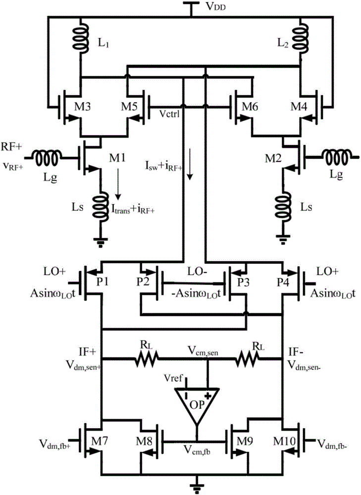
[0026] The schematic diagram of the circuit structure of the above-mentioned direct conversion radio frequency receiving front-end circuit device is as follows: figure 2 As shown, the specific driver stage circuit 1 is used to connect with the switch pair circuit 2, including NMOS transistors M1-M6, which convert the small signal voltage vRF into a small signal current iRF, and the small signal current iRF is converted through the NMOS transistors. The signal current iRF is folded and flows into the source of the PMOS transistor in the switch pair circuit;

[0027] The swi...


PUM


Abstract

The embodiment of the invention provides a direct-conversion radio frequency receiving front-end circuit device. The device comprises a driving stage circuit, a switch pair circuit and a load circuit; the driving stage circuit converts a small signal voltage vRF into small signal current iRF, and folds the small signal current iRF to make the small signal current iRFflow into a source electrode of a PMOS tube in the switch pair circuit through an NMOS tube; the switch pair circuit carries out frequency conversion processing on the small signal current iRF through the PMOS tube to obtain medium frequency small signal current and transmits the medium frequency small signal current to the load circuit; and the load circuit converts the medium frequency small signal current into a medium frequency small signal voltage and outputs the medium frequency small signal voltage. The direct-conversion radio frequency receiving front-end circuit device provided by the embodiment of the invention reduces the noise in a similar current injection mode to improve the overall performance of the circuit. A folded structure is employed to increase an additional branch from the power supply to the ground, in other words, the optimization degree of freedom of bias current is correspondingly increased. The bias current of a switch pair is reduced to improve the flicker noise performance, and meanwhile, the direct-conversion radio frequency receiving front-end circuit device has excellent gain performance.

Description

technical field [0001] The invention relates to the technical field of radio frequency reception, in particular to a front-end circuit device for direct frequency conversion radio frequency reception. Background technique [0002] In the past ten years, the important research directions of the RF receiving front-end mainly include low-voltage and low-power implementation technology, low-noise implementation technology, high-linearity implementation technology, ultra-wideband implementation method, ultra-high-frequency application implementation, and system monolithic integration. In addition to using ever-shrinking process sizes and high characteristic frequency three-five-point semiconductor devices to obtain good circuit high-frequency performance, there are various technical methods such as current multiplexing, capacitive cross-coupling common-gate input, Derivative superposition, filter termination to obtain good electrical performance. The direct conversion receiving ...

Claims


Application Information

Patent Timeline
Patent Type & Authority Applications(China)
IPC IPC(8): H04B1/10H04B1/16
Inventor 刘振徐树民田心亓延峰
Owner AEROSPACE INFORMATION
Why Eureka
Try Eureka