Continuous purification treatment system for paint spraying waste gas and purification method adopting continuous purification treatment system

A treatment system and exhaust gas purification technology, applied in gas treatment, chemical instruments and methods, separation methods, etc., can solve the problems affecting the promotion of painting exhaust gas VOCs treatment technology, high investment and operation and maintenance costs, and high operation and maintenance requirements. Achieve the effect of alleviating economic and environmental pressure, flexible use, low investment and operation and maintenance costs

Inactive Publication Date: 2016-06-29
CHONGQING NEW BELL ENVIRONMENTAL PROTECTION TECH CO LTD
View PDF5 Cites 0 Cited by
  • Summary
  • Abstract
  • Description
  • Claims
  • Application Information

AI Technical Summary

Problems solved by technology

However, the commonly used technologies have the following defects: the problem of the adsorption concentration + oxidation combustion method in the treatment of spray paint exhaust gas is the high requirements for operation and maintenance, and the high investment and operation and maintenance costs; Regenerative combustion RTO and heat recovery thermal incineration TNV methods generally require The use of gas requires high combustion control and secondary pollution; the regenerative catalytic RCO method requires the use of expensive and easily deactivated catalysts, and finally deactivated catalysts must be treated harmlessly to avoid secondary pollution
These factors have affected the promotion of spray paint exhaust gas VOCs treatment technology

Method used


Image

  • Continuous purification treatment system for paint spraying waste gas and purification method adopting continuous purification treatment system
  • Continuous purification treatment system for paint spraying waste gas and purification method adopting continuous purification treatment system

Examples


Embodiment Construction

[0035] The specific implementation manner and working principle of the present invention will be further described in detail below in conjunction with the accompanying drawings.

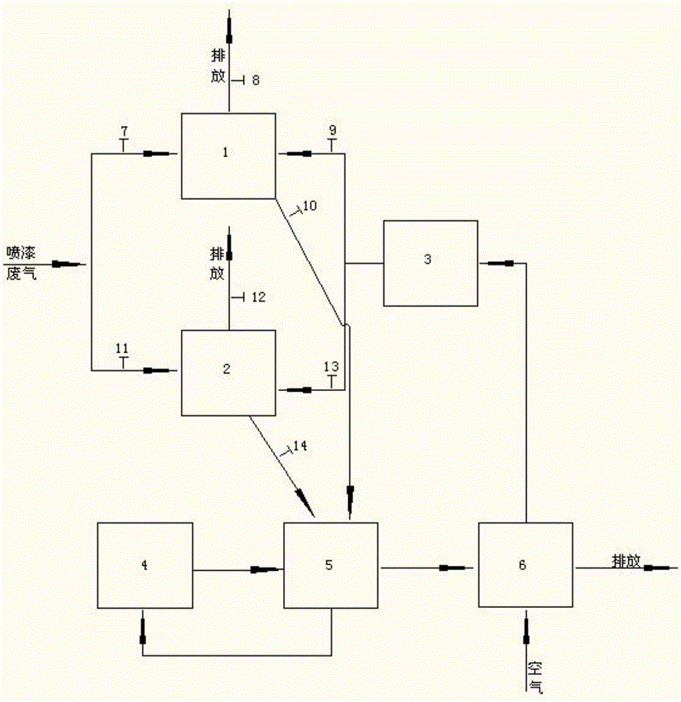
[0036] like figure 1 As shown, a continuous treatment system for spray paint waste gas purification includes a first adsorption zone 1, a second adsorption zone 2, a preheating zone 3 and a thermal decomposition zone 4, and the waste gas in the first adsorption zone 1 and the second adsorption zone 2 The inlet is used to collect the waste gas from spray painting, and the waste gas outlets of the first adsorption area 1 and the second adsorption area 2 both discharge the exhaust gas after adsorption treatment through the discharge pipe, and the first adsorption area 1 and the second adsorption area 2 The desorption hot air inlets are all connected to the outlet of the preheating zone 3, and the hot air outlets of the first adsorption zone 1 and the second adsorption zone 2 are connected to the first h...


PUM


Abstract

The invention discloses a continuous purification treatment system for paint spraying waste gas and a purification method adopting the continuous purification treatment system. The system comprises a first adsorption zone, a second adsorption zone, a preheating zone and a thermal decomposition zone, wherein waste gas inlets of the first adsorption zone and the second adsorption zone are used for collecting the paint spraying waste gas; waste gas exhaust ports of the first adsorption zone and the second adsorption zone are used for discharging waste gas subjected to adsorption treatment through discharging pipelines; desorption hot air inlets of the first adsorption zone and the second adsorption zone are connected onto an outlet of the preheating zone; hot air outlets of the first adsorption zone and the second adsorption zone are connected to a first heat recovery zone; an outlet of the first heat recovery zone is connected with the thermal decomposition zone; an outlet of the thermal decomposition zone is used for recovering heat of the gas subjected to thermal decomposition through the first heat recovery zone and discharging the gas. The system and the method have the remarkable effects as follows: requirements for operation and maintenance are lower; the investment and the operating cost are low; the adsorption process can be performed continuously; the treatment efficiency of the paint spraying waste gas is high.

Description

technical field [0001] The invention relates to the technical field of atmospheric environment protection, in particular to a continuous treatment system for purifying exhaust gas from spray paint and a purification method thereof. Background technique [0002] With the increase of environmental protection requirements and investment in environmental protection year by year, the improvement of atmospheric environmental quality is not obvious, and smog occurs frequently in various places. After SO2, NOx and dust became the control objects, volatile organic compounds (VOCs) were also included in the scope of air pollutant control. [0003] In the existing technology, VOCs treatment technologies mainly include activated carbon adsorption, condensation recovery, adsorption concentration + oxidation combustion (regenerative combustion RTO, heat recovery thermal incineration TNV or regenerative catalytic RCO), low temperature plasma, photocatalysis and biological methods, etc. Am...

Claims


Application Information

Patent Timeline
Patent Type & Authority Applications(China)
IPC IPC(8): B01D53/04B01D53/00
CPCB01D53/0407B01D53/005B01D2253/102B01D2253/106B01D2257/708B01D2259/40003B01D2259/4009
Inventor 李云涛
Owner CHONGQING NEW BELL ENVIRONMENTAL PROTECTION TECH CO LTD
Why Eureka
Try Eureka