Forming method for amorphous alloy component

A technology for amorphous alloys and components, which is applied in metal processing equipment, equipment for feeding molten metal into casting molds, and casting molten material containers, etc. It can solve the strict requirements of temperature control and deformation time, and can not meet the requirements of product use. , The product is prone to crystallization and other problems, and achieves the effect of low solidification shrinkage coefficient, high production efficiency and good product quality.

Active Publication Date: 2016-06-29
INST OF METAL RESEARCH - CHINESE ACAD OF SCI +1
View PDF7 Cites 7 Cited by
  • Summary
  • Abstract
  • Description
  • Claims
  • Application Information

AI Technical Summary

Problems solved by technology

This method first needs to obtain an amorphous base material, so the preparation process is complicated, the efficiency is low, and the requirements for temperature control and deformation time are relatively strict. Otherwise, the product is prone to crystallization, and the final performance will deteriorate, which cannot meet the use requirements of the product.

Method used


Image

  • Forming method for amorphous alloy component
  • Forming method for amorphous alloy component
  • Forming method for amorphous alloy component

Examples


Embodiment 1

[0023] The forming process of this embodiment is specifically as follows:

[0024] 1. Master alloy composition: Ti32.8Zr30.2Ni5.3Cu9Be22.7 (atomic percentage).

[0025] 2. Master alloy smelting: the alloy is prepared according to the design composition, then placed in the crucible, and vacuumed to 5×10- 1 ~5×10 -3 Pa (can also be filled with inert protective gas), use induction melting or arc melting technology to obtain master alloy with uniform composition, and cast into regular master alloy ingot (such as rod, plate or sheet, etc.).

[0026] 3. Master alloy cutting: According to the quality of amorphous alloy components, cutting equipment is used to cut the cast alloy ingot into the required size.

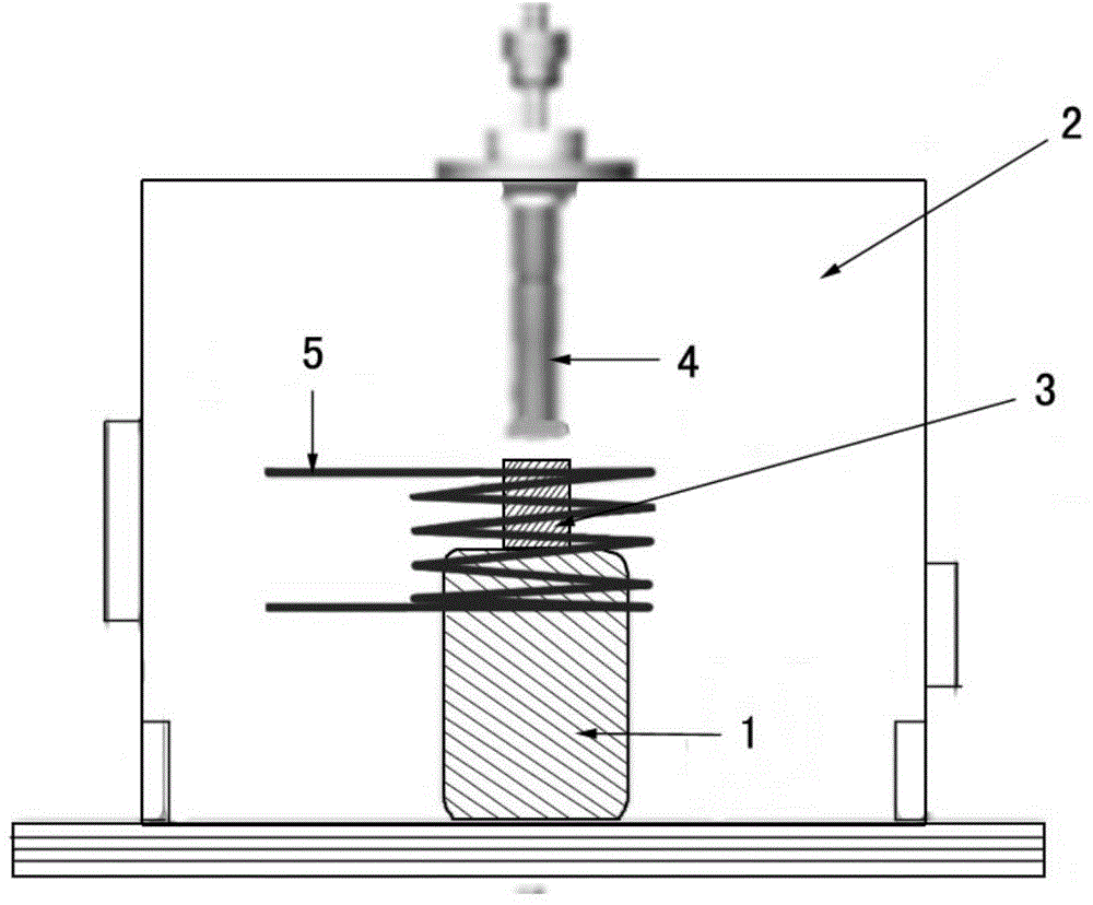
[0027] 4. Forming and processing of amorphous alloy components: place the cut master alloy on the melting platform and vacuumize to 1×10 -1 ~1×10 -3 Pa (can also be filled with inert protective gas), use induction heating (arc heating or laser heating and other heating metho...

Embodiment 2

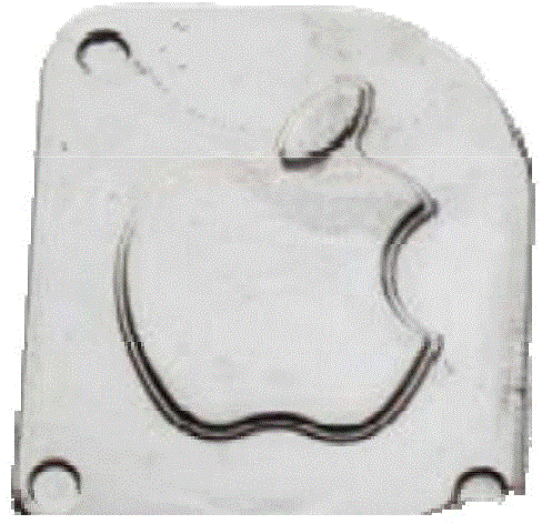
[0029] The difference from Example 1 is that the selected master alloy composition is Zr54.73Cu29.75Ni4.97Al9.95Ag0.1Y0.5 (atomic percentage), and the components of pure amorphous structure are obtained such as image 3 shown.

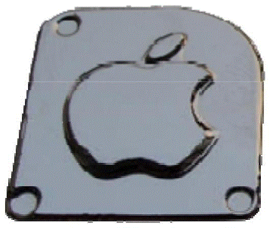
[0030] Depend on Figure 2-3 It can be seen that the surface finish of the amorphous alloy component prepared by the present invention is good and the dimensional accuracy is high, and by SEM observation and analysis, the component interior is dense and free of defects such as shrinkage cavities ( Figure 4 ).

[0031] The alloy components of the present invention can be all amorphous alloy systems, such as Ti-based amorphous alloys, Zr-based amorphous alloys, Fe-based amorphous alloys, Ni-based amorphous alloys, Mg-based amorphous alloys, Pd-based amorphous alloys, Ag-based amorphous alloy, Hf-based amorphous alloy, Pt-based amorphous alloy and other amorphous alloy components.


PUM


Abstract

The invention discloses a forming method for an amorphous alloy component, and belongs to the technical field of amorphous alloy. According to the method, in the temperature interval of the condensation process of amorphous alloy melt, namely the temperature range from liquidus (T1) to glass transition (Tg), low-pressure precise formation is carried out on the amorphous alloy. The technology makes full use of the characteristics that the smooth free surface formed after the alloy melt is condensed, the deformation feature is good and the condensation shrink factor is low, and the obtained amorphous alloy component is high in size accuracy, good in surface smoothness, internally compact and free of shrinking holes or shrinkage porosity and other defects. The process of the technical method is short, production efficiency is high, cost is reduced, and product quality is good.

Description

technical field [0001] The invention relates to the technical field of amorphous alloys, in particular to a method for forming amorphous alloy components. Background technique [0002] Due to its unique structural characteristics, amorphous composite materials have special properties, such as high specific strength, high wear resistance, high corrosion resistance, unique deformation characteristics, etc. It has broad application prospects in aerospace materials, defense industry, consumer electronics and other fields. At present, the preparation technology of amorphous alloy components mainly includes two types, one is vacuum die casting forming technology, by filling the alloy melt into the cavity under a certain pressure, and then cooling it, that is, the liquidus temperature is filled shape and shape. This method can obtain parts with complex structure, fast and efficient, and has good formability. However, the disadvantage of this method is that pores are easy to form ...

Claims


Application Information

Patent Timeline
Patent Type & Authority Applications(China)
IPC IPC(8): B22D17/00B22D35/00C22C1/03
CPCB22D17/00B22D17/02B22D27/15B22D41/005C22C45/00C22C45/10
Inventor 张海峰付华萌朱正旺王爱民李宏张宏伟李扬德李卫荣汤铁装杨洁丹
Owner INST OF METAL RESEARCH - CHINESE ACAD OF SCI
Why Eureka
Try Eureka