Method and device for recycling mixed refrigerant refrigeration natural gas light hydrocarbon

A mixed refrigerant and light hydrocarbon recovery technology, applied in refrigeration and liquefaction, cold treatment separation, liquefaction, etc., can solve the problems of poor load regulation ability, complex process flow, high energy consumption, etc., achieve uniform temperature difference, high C3 yield, The effect of low cooling temperature

Active Publication Date: 2016-06-29
CHENGDU SEPMEM SCI & TECH
View PDF7 Cites 15 Cited by
  • Summary
  • Abstract
  • Description
  • Claims
  • Application Information

AI Technical Summary

Problems solved by technology

[0006] The purpose of the invention of the present invention is: exist C for existing natural gas light hydrocarbon recovery method 3 To solve the problems of low yield, complex process flow, poor load regulation ability, and high energy consumption, a method and device for recovering light hydrocarbons from mixed refrigerant refrigeration natural gas are provided.

Method used


Image

  • Method and device for recycling mixed refrigerant refrigeration natural gas light hydrocarbon
  • Method and device for recycling mixed refrigerant refrigeration natural gas light hydrocarbon

Examples


Embodiment 1

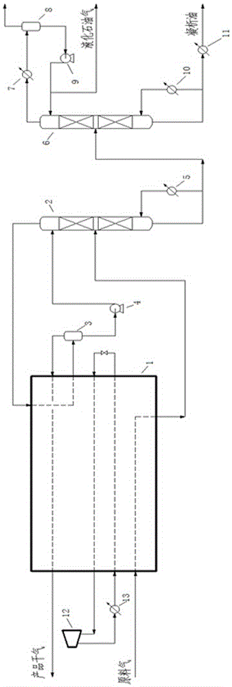
[0039] The flow chart of this embodiment is as follows figure 1 As shown, the workflow of this embodiment is as follows.

[0040]The raw material gas enters the main heat exchanger 1, and after being cooled and partially condensed, enters the deethanizer 2 from the middle part of the deethanizer 2 for separation. The gas phase separated from the top of the deethanizer 2 enters the main heat exchanger 1 for cooling and partial condensation, and then enters the deethanizer top separator 3 at the top of the deethanizer 2 for gas-liquid separation to obtain low-temperature product gas 1. The liquid phase material is refluxed at the top of the tower, and the low-temperature product gas (mainly composed of C1 and C2 hydrocarbons) is reheated by the main heat exchanger 1 to obtain the product gas. The top reflux liquid phase material (mainly composed of C3 and above hydrocarbons) is pressurized by the deethanizer top reflux pump 4, and returns to the deethanizer 2 from the upper par...

Embodiment 2

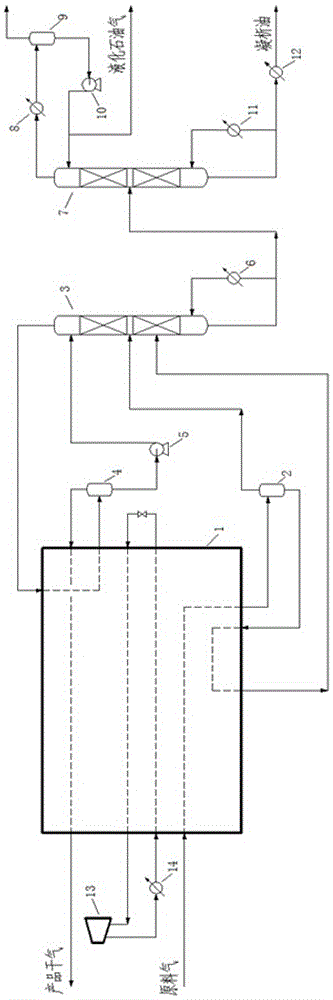
[0047] The flow chart of this embodiment is as follows figure 2 As shown, the workflow of this embodiment is as follows.

[0048] The raw material gas enters the main heat exchanger 1, and after being cooled and partially condensed, it enters the low-temperature separator 2 for primary separation to obtain the primary gas phase and liquid phase respectively, and the primary gas phase enters the deethanizer from the middle of the deethanizer 3 3 for separation, the primary liquid phase is returned to the main heat exchanger 1 for reheating to obtain the first reheated material, and the first reheated material enters the deethanizer 3 from the lower part of the deethanizer 3 for separation.

[0049] The gas phase drawn from the top of the deethanizer 3 enters the main heat exchanger 1 for cooling and partial condensation, and then enters the deethanizer top separator 4 for gas-liquid separation to obtain low-temperature product gas and top reflux liquid phase materials respecti...


PUM


Abstract

The invention discloses a method and device for recycling mixed refrigerant refrigeration natural gas light hydrocarbon, and belongs to the field of natural gas light hydrocarbon recycling. The method and device aim at solving the problems that according to an existing natural gas light hydrocarbon recycling method, the C3 recycling rate is low, the technological process is complex, the load adjusting capacity is poor, and energy consumption is high. According to the method and device, feed gas enters a main heat exchanger, is subject to partial condensation and then enters a deethanization tower; a gas phase produced from the tower top of the deethanization tower is subject to reheating through the main heat exchanger and then is transported outwards as product gas, and a liquid phase guided out from the tower bottom of the deethanization tower enters a debutanization tower; and a liquefied petroleum gas product is obtained from the tower top of the debutanization tower, and a condensate oil product is obtained from the tower bottom of the debutanization tower. The cold amount needed in the light hydrocarbon recycling process is provided by a mixed refrigerant refrigeration system. The method and device have the beneficial effects of being high in C3 recycling rate, flexible in operation, high in raw material adaptability, low in energy consumption, simple in flow, small in investment and the like, has the good application prospects, and is worth of large-scale application and popularization.

Description

technical field [0001] The invention relates to the field of natural gas, in particular to the field of condensation and separation of natural gas, in particular to a method and device for recovering light hydrocarbons from mixed refrigerant refrigeration natural gas. Background technique [0002] Light hydrocarbon recovery refers to the process of recovering components heavier than methane or ethane in natural gas in liquid form. Through the recovery of light hydrocarbons, on the one hand, the hydrocarbon dew point of natural gas can be controlled to achieve the commercial gas quality index and avoid gas-liquid two-phase flow; on the other hand, the recovered liquid hydrocarbons have great economic value and can be directly used as fuel. It can be further separated into ethane, propane, butane or mixture of propane and butane (liquefied gas), light oil and other chemical raw materials. [0003] At present, light hydrocarbon recovery methods mainly include adsorption method...

Claims


Application Information

Patent Timeline
Patent Type & Authority Applications(China)
IPC IPC(8): F25J3/02F25J3/06
CPCF25J3/0209F25J3/061F25J3/0233F25J3/0242F25J2200/02F25J2200/74F25J2205/04F25J2215/64F25J2270/12F25J2270/66
Inventor 张惊涛母斌
Owner CHENGDU SEPMEM SCI & TECH
Why Eureka
Try Eureka