Double-side laser welding method for powder metallurgy control

A technology of laser welding and powder metallurgy, which is applied in laser welding equipment, welding equipment, metal processing, etc., can solve the problems that welding wire elements cannot be controlled by welding seam alloys, etc., and achieve uniform distribution of deposition layer elements, simple structure, and no density. The effect of defects

Active Publication Date: 2016-07-06
HARBIN INST OF TECH
View PDF8 Cites 12 Cited by
  • Summary
  • Abstract
  • Description
  • Claims
  • Application Information

AI Technical Summary

Problems solved by technology

[0005] In order to solve the problem that the welding wire elements cannot fully regulate the weld structure in the process of double-sided laser welding of T-shaped structures, the present invention proposes a double-sided laser welding method controlled by powder metallurgy

Method used


Image

  • Double-side laser welding method for powder metallurgy control
  • Double-side laser welding method for powder metallurgy control
  • Double-side laser welding method for powder metallurgy control

Examples


specific Embodiment approach 1

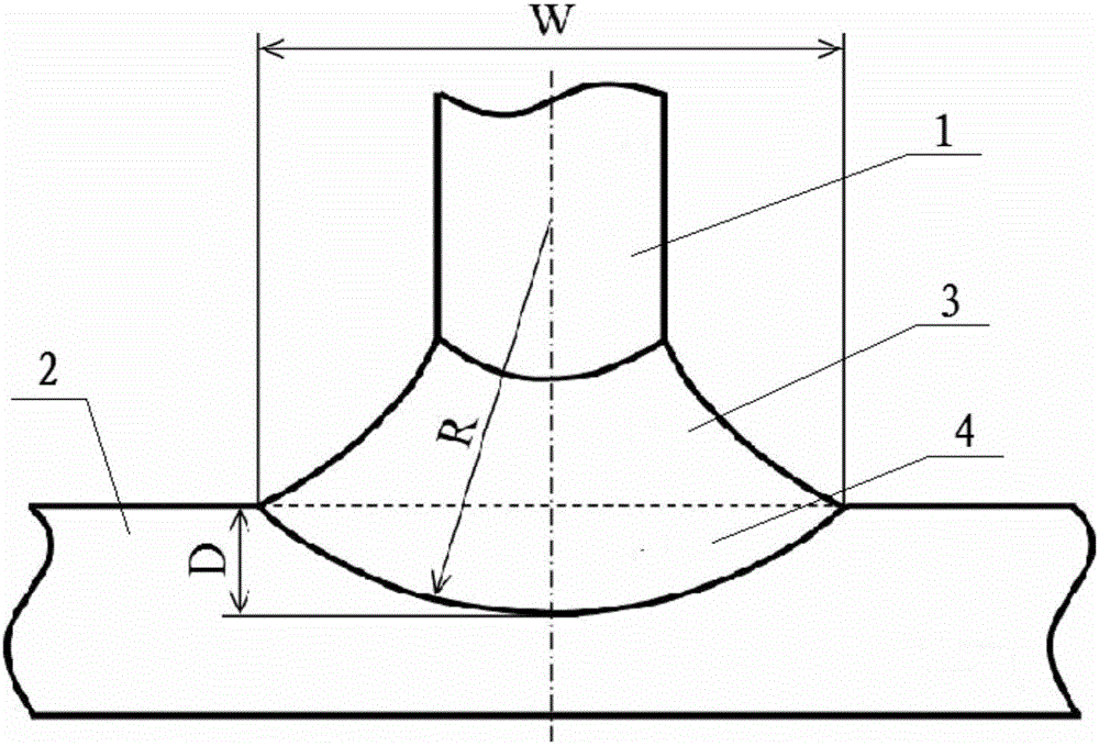
[0020] Specific implementation mode one: combine Figure 1 to Figure 5 Illustrate this embodiment, the welding method of this embodiment is to the welding of T-shaped structure of aircraft wall plate, this T-shaped structure is welded by vertical long stringer 1 and horizontally placed skin 2, and concrete welding method is through This is achieved by the following steps:

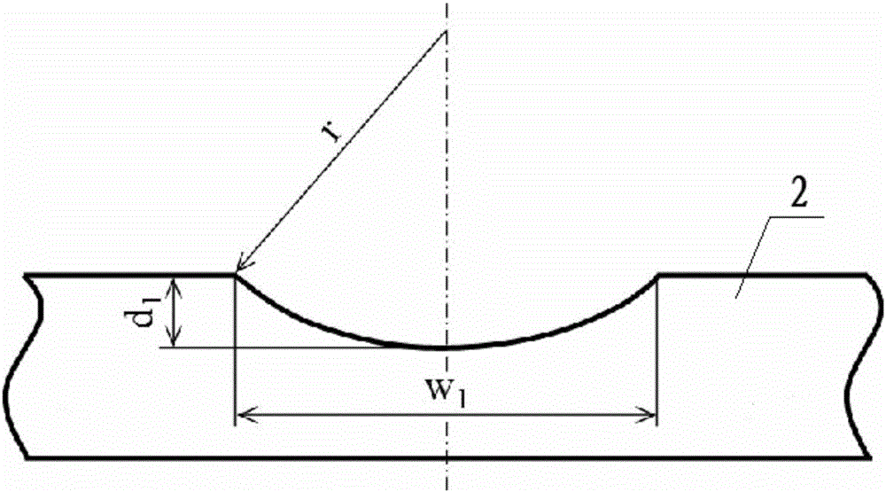
[0021] Step 1. Machining the groove 5: Mechanically milling the groove 5 along the welding direction at the center of the upper surface of the skin 2 to be welded. The cross section of the groove 5 is arc-shaped, and the radius of curvature r of the groove 5 is equal to the curvature of the lower fusion line Radius R, groove 5 maximum depth d 1 Less than the maximum penetration D of the weld skin side 4, the maximum width w of the groove 5 1 If it is less than the maximum weld width W of the weld, chemically clean the skin 2 to remove the oxide film and processing stains; select a suitable milling cutter ...

specific Embodiment approach 2

[0024] Specific implementation mode two: combination figure 1 and Figure 4 Describe this embodiment. In this embodiment, the thickness of the girder 1 and the skin 2 are both 2 mm, the control range of the maximum penetration depth D of the skin side 4 of the weld seam is 0.5 mm to 1.0 mm, and the control range of the maximum fusion width W of the weld seam is 2.5 mm. mm~3.0mm, maximum groove depth d 1 Satisfies the relationship with the maximum penetration D of the weld skin side 4: d 1 =0.8D, the maximum groove width w 1 Satisfies the relationship with the maximum weld width W of the weld: w 1 = 0.8W. Other steps are the same as in the first embodiment.

specific Embodiment approach 3

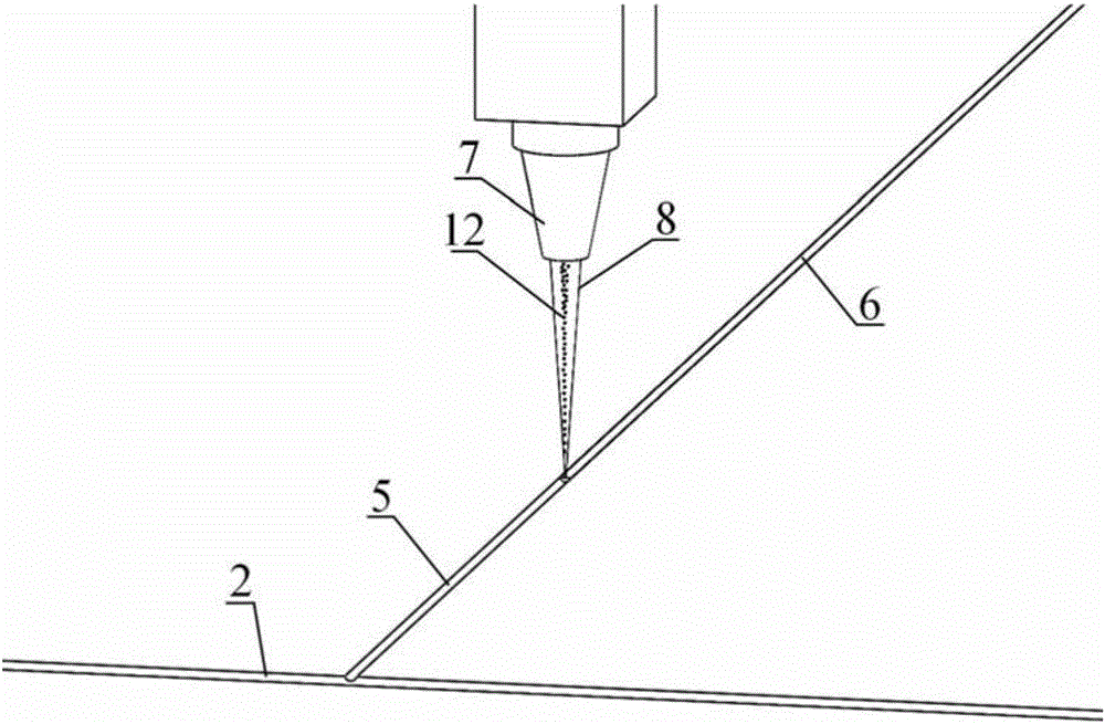
[0025] Specific implementation mode three: combination image 3 , Figure 4 and Figure 5 Describe this implementation mode. In this implementation mode, the cross-sectional area of ​​the groove 5 in step 2 should be equal to the cross-sectional area of ​​the deposition layer 6 . Other steps are the same as those in Embodiment 1 or 2.


PUM

PropertyMeasurementUnit
thicknessaaaaaaaaaa

Abstract

The invention discloses a double-side laser welding method for powder metallurgy control, relates to a double-laser beam welding method, and solves the problem that welding wire elements cannot perform full alloy control for a welding line structure in the double-side laser welding process of a T-shaped structure. The method comprises the following steps: (1) a groove is mechanically milled in the center of a position to be welded on the upper surface of a cover in the welding direction; and the cover is chemically cleaned to remove an oxide film and machining stains; (2) alloy powder is prefilled in the groove to form a deposition layer; a laser cladding head is vertically placed rightly above the groove; the laser powder feeding material adding is performed on the surface of the groove to obtain the deposition layer by using a mode of coaxial feeding of laser beams and the alloy powder; and a deposition material higher than the surface of the cover is grinded off by using a grinding machine, so that a deposition surface is coplanar with the surface of the cover; and (3) the double-laser wire filling welding is performed for a long purlin and the cover to obtain symmetric welding lines on two sides. The method is used for double-laser beam welding of the T-shaped structure.

Description

technical field [0001] The invention relates to a double-laser beam welding method, in particular to a double-side laser welding method controlled by powder metallurgy, which can be applied to the welding process of long stringers and skins in the manufacturing process of aircraft wall panels. Background technique [0002] There are a large number of skin-elongated T-shaped structures in the aircraft fuselage panels, and this T-shaped structure is mainly assembled and connected by riveting technology. In the early 1990s, Airbus Corporation of Germany took the lead in carrying out the research on double-sided laser simultaneous welding technology, and successfully welded the T-shaped structure. Compared with traditional riveting technology, double-sided laser simultaneous welding technology has higher production efficiency, especially can greatly reduce the weight of the fuselage and improve the fuel economy of the aircraft. At present, this innovative technology has been su...

Claims


Application Information

Patent Timeline
Patent Type & Authority Applications(China)
IPC IPC(8): B23K26/24B23K26/06B23K26/12B23K26/60
CPCB23K26/0608B23K26/123B23K26/211B23K26/24B23K26/60B23K2101/006
Inventor 陶汪韩冰陈彦宾
Owner HARBIN INST OF TECH
Why Eureka
Try Eureka