A double-sided laser welding method controlled by powder metallurgy
A laser welding and powder metallurgy technology, used in laser welding equipment, welding equipment, metal processing and other directions, can solve the problem that the welding wire elements cannot be controlled by the alloy of the weld structure, and achieve uniform distribution of elements in the deposition layer, density without defects, and matching. more flexible effect
- Summary
- Abstract
- Description
- Claims
- Application Information
AI Technical Summary
Problems solved by technology
Method used
Image
Examples
specific Embodiment approach 1
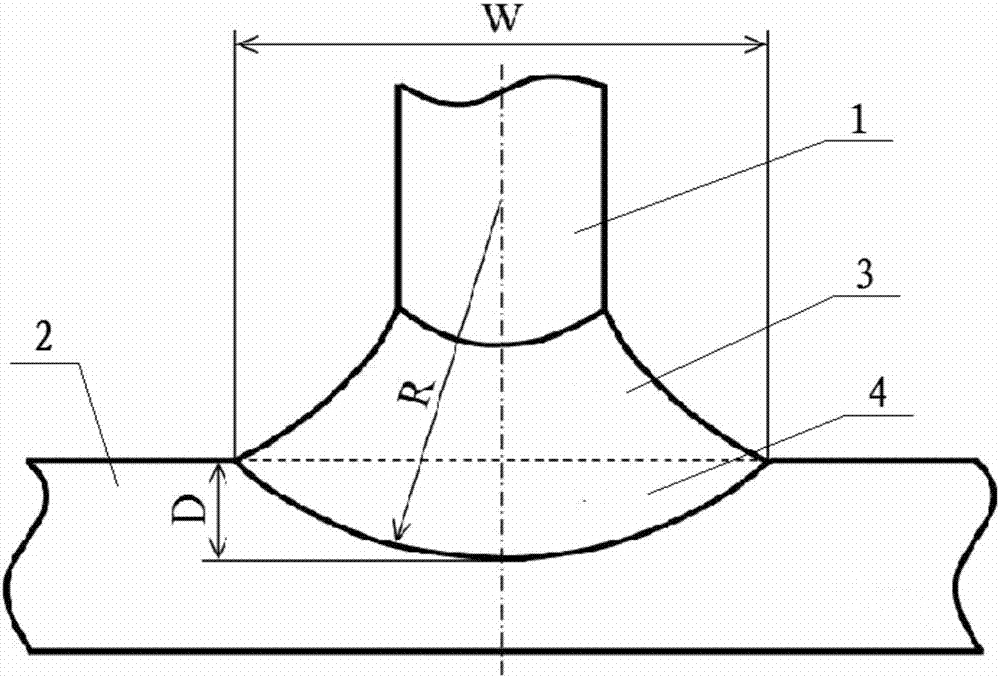
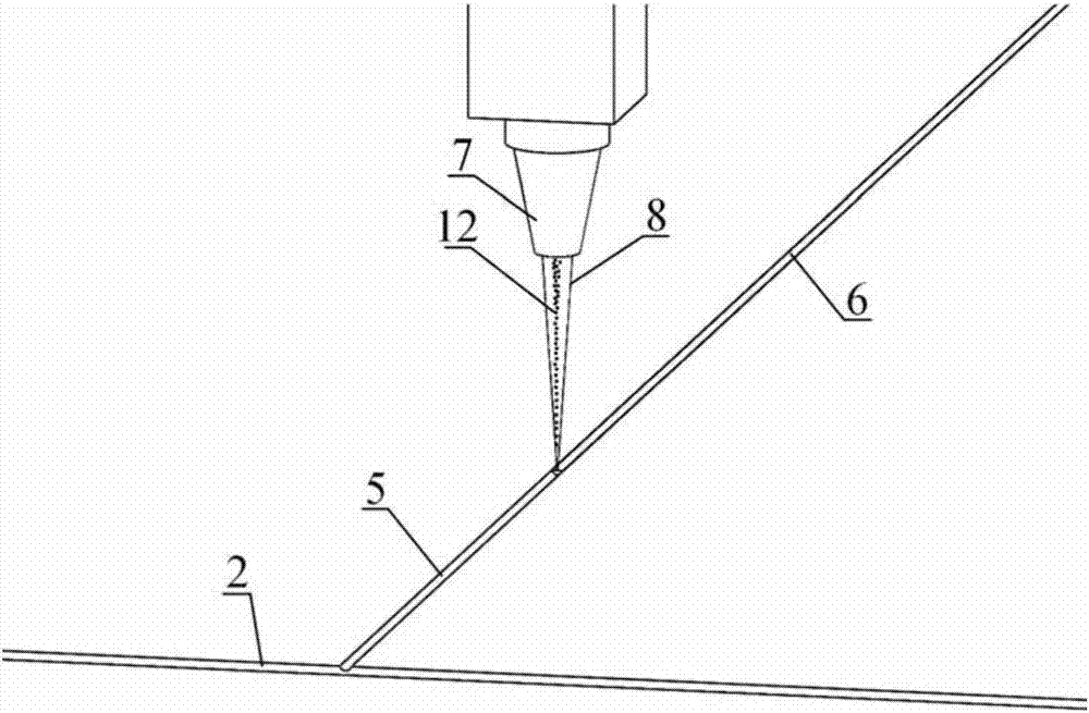
[0020] Specific implementation mode one: combine Figure 1 to Figure 5 Illustrate this embodiment, the welding method of this embodiment is to the welding of T-shaped structure of aircraft wall plate, this T-shaped structure is welded by vertical long stringer 1 and horizontally placed skin 2, and concrete welding method is through This is achieved by the following steps:
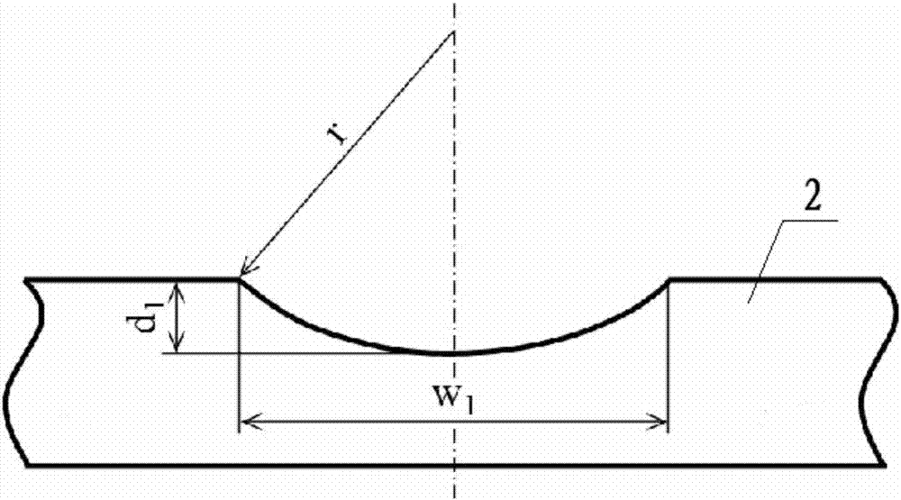
[0021] Step 1. Machining the groove 5: Mechanically milling the groove 5 along the welding direction at the center of the upper surface of the skin 2 to be welded. The cross section of the groove 5 is arc-shaped, and the radius of curvature r of the groove 5 is equal to the curvature of the lower fusion line Radius R, groove 5 maximum depth d 1 Less than the maximum penetration D of the weld skin side 4, the maximum width w of the groove 5 1 If it is less than the maximum weld width W of the weld, chemically clean the skin 2 to remove the oxide film and processing stains; select a suitable milling cutter ...
specific Embodiment approach 2
[0024] Specific implementation mode two: combination figure 1 and Figure 4 Describe this embodiment. In this embodiment, the thickness of the girder 1 and the skin 2 are both 2 mm, the control range of the maximum penetration depth D of the skin side 4 of the weld seam is 0.5 mm to 1.0 mm, and the control range of the maximum fusion width W of the weld seam is 2.5 mm. mm~3.0mm, maximum groove depth d 1 Satisfies the relationship with the maximum penetration D of the weld skin side 4: d 1 =0.8D, the maximum groove width w 1 Satisfies the relationship with the maximum weld width W of the weld: w 1 = 0.8W. Other steps are the same as in the first embodiment.
specific Embodiment approach 3
[0025] Specific implementation mode three: combination image 3 , Figure 4 and Figure 5 Describe this implementation mode. In this implementation mode, the cross-sectional area of the groove 5 in step 2 should be equal to the cross-sectional area of the deposition layer 6 . Other steps are the same as those in Embodiment 1 or 2.
PUM
| Property | Measurement | Unit |
|---|---|---|
| thickness | aaaaa | aaaaa |
Abstract
Description
Claims
Application Information
 - R&D
- Intellectual Property
- Life Sciences
- Materials
- Tech Scout
- Unparalleled Data Quality
- Higher Quality Content
- 60% Fewer Hallucinations
Browse by: Latest US Patents, China's latest patents, Technical Efficacy Thesaurus, Application Domain, Technology Topic, Popular Technical Reports.
© 2025 PatSnap. All rights reserved.Legal|Privacy policy|Modern Slavery Act Transparency Statement|Sitemap|About US| Contact US: help@patsnap.com


