
Gas burner and burning method achieving ultra-low nitrogen oxide emission

A gas burner and nitrogen oxide technology, which is applied in combustion methods, gas fuel burners, burners, etc., can solve the problems of increased combustion temperature excess air coefficient, complex system, large investment, etc., and achieves suppression of nitrogen oxide emissions. , the effect of low residual oxygen content and high flue gas temperature

Inactive Publication Date: 2016-07-27
王建学
View PDF0 Cites 9 Cited by
  • Summary
  • Abstract
  • Description
  • Claims
  • Application Information

AI Technical Summary

Problems solved by technology

For fuel and air pretreatment methods and flue gas treatment methods, due to the complexity of the system, large investment, large land occupation, and high operating costs, it is not suitable for relatively dispersed users and burners with low power.
While suppressing the formation of nitrogen oxides, low-nitrogen burners are often accompanied by reduced combustion efficiency, reduced combustion temperature, or increased excess air coefficient, resulting in reduced combustion efficiency and increased operating costs.
At present, the most widely used flue gas recirculation method in low nitrogen oxide emission combustion technology still has the following problems: 1. The flue gas recirculation is obtained by high-speed air jet injection, and the amount of flue gas circulation is difficult to control; 2. The flue gas circulation After cooling, a large amount of condensed water is produced, which reduces the service life of fans and burners; 3. When the proportion of circulating flue gas is small, the emission reduction effect is limited, and when the proportion of circulating flue gas is large, the combustion is unstable

Method used


Image

  • Gas burner and burning method achieving ultra-low nitrogen oxide emission
  • Gas burner and burning method achieving ultra-low nitrogen oxide emission
  • Gas burner and burning method achieving ultra-low nitrogen oxide emission

Examples


Embodiment Construction

[0028] Below in conjunction with accompanying drawing and specific embodiment, further illustrate the present invention, should be understood that these embodiments are only for illustrating the present invention and are not intended to limit the scope of the present invention, after having read the present invention, those skilled in the art will understand various aspects of the present invention Modifications in equivalent forms all fall within the scope defined by the appended claims of this application.

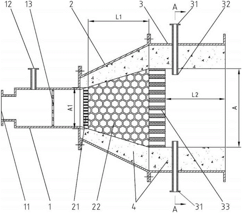
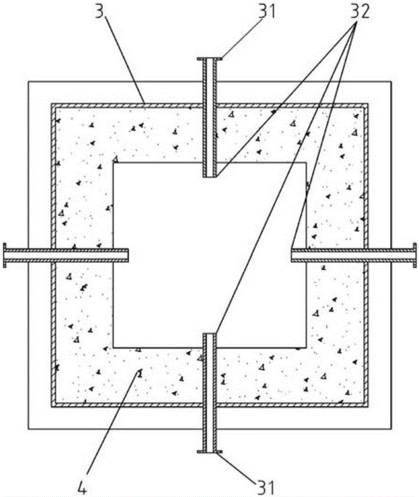
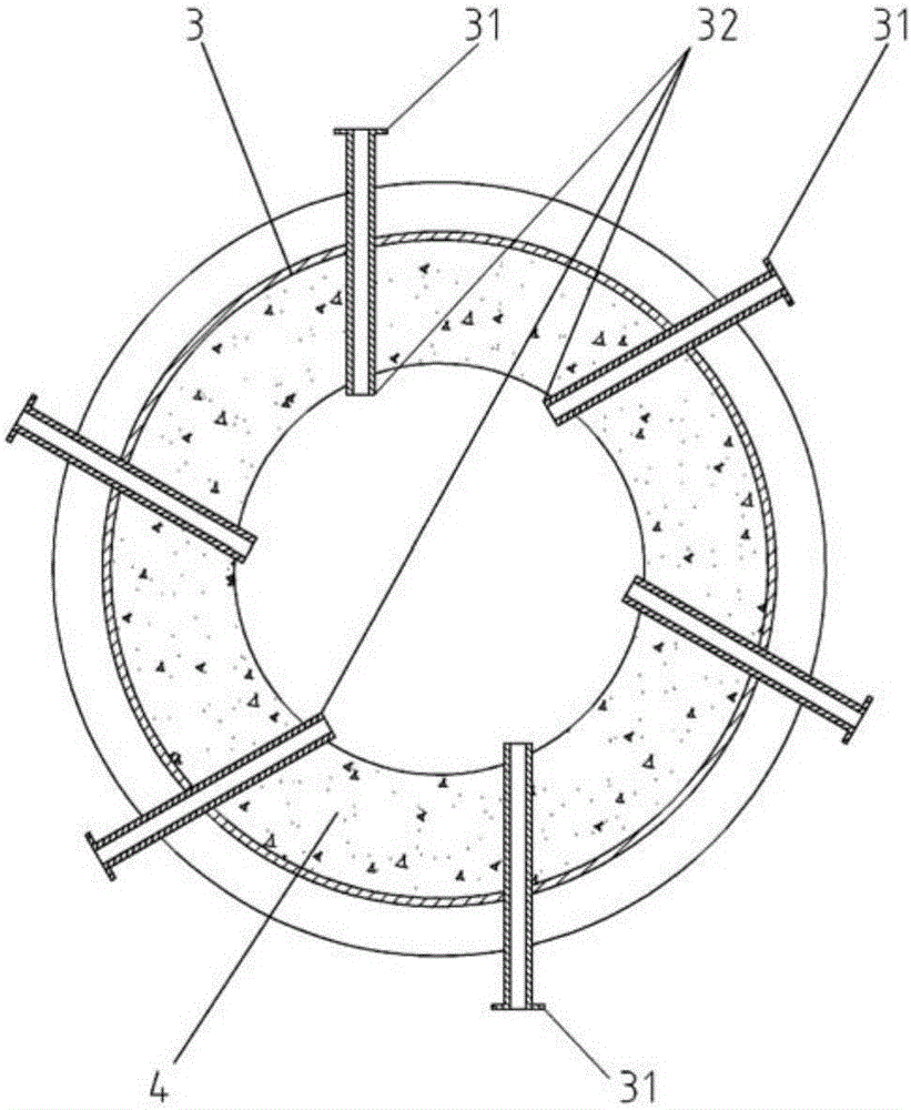
[0029] Such as figure 1 As shown, the present invention includes mixer 1, premix combustion section 2 and supplementary combustion section 3 three parts.

[0030] The front end of the mixer 1 is provided with a combustion air interface 11 , its upper part is provided with a primary fuel interface 12 , and the rear end is connected with the premixing combustion section 2 . A perforated plate 13 is arranged inside the mixer 1 to help the air and primary fuel to mix evenly...


PUM


Abstract

The invention relates to the technical field of energy conservation, emission reduction and low-pollution burning, in particular to a gas burner and burning method achieving ultra-low nitrogen oxide emission. The gas burner achieving ultra-low nitrogen oxide emission comprises a mixer, a pre-mixing burning section and an after-burning section. Total gas is divided into primary fuel and secondary fuel; the primary fuel accounts for 25%-55% of the total gas and is evenly mixed with total combustion-supporting air, and emission of nitric oxide is restrained through the low-fuel-concentration pre-mixing burning principle; the secondary fuel accounts for 45%-75% of the total gas, and emission of the nitric oxide is restrained through the low-oxygen-concentration diffusive burning principle; and meanwhile the low content of residual oxygen in a burnt product is ensured, and the temperature of exhaust gas is high. In the pre-mixing burning section, ceramic porous filler is used as a medium for stable flames, and the stability of low-fuel-concentration pre-mixing burning is achieved; and the ceramic porous filler is of a divergent structure, so that tempering is effectively avoided, and safety is improved. Compared with a conventional burning mode, the nitrogen oxide emission can be reduced by 50%-90%, and the nitrogen oxide emission concentration under rated loads is lower than 30 mg / m<3>.

Description

technical field [0001] The invention relates to the technical field of energy saving, emission reduction and low-pollution combustion, in particular to a gas burner and a combustion method for reducing nitrogen oxide emissions. Under the premise of not affecting the combustion efficiency and operating cost of the burner, it is compared with conventional combustion methods It can reduce the emission of nitrogen oxides in combustion flue gas by 50% to 90%, and the concentration of nitrogen oxides emitted by the burner at rated load is lower than 30mg / m 3 . Background technique [0002] The current research on low-NOx emission combustion technology is divided into three directions: pretreatment of fuel and air; optimal configuration of air and fuel and burner structure design; post-treatment of flue gas. For fuel and air pretreatment methods and flue gas treatment methods, due to complex systems, large investment, large land occupation, and high operating costs, they are not s...

Claims


Application Information

Patent Timeline
IPC IPC(8): F23D14/02F23D14/12F23D14/62F23D14/46F23L9/00
CPCF23D14/02F23D14/12F23D14/46F23D14/62F23L9/00
Inventor 王建学萧琦
Owner 王建学
Learn More