
12kV current-carrying 1250A solid insulation switchgear

A solid-insulated switch and current-carrying technology, applied in switchgear, switchgear setting, switchgear setting with resin casing, etc., can solve the problem of insufficient distance between connecting busbars, too many edges and corners of conductive parts, and deformation of key parts. Aging and other problems, to achieve the effect of improving the ability and service life of breaking current, avoiding uneven conduction problems, and high dielectric strength recovery speed

Active Publication Date: 2016-08-10
GUANGDONG PURLUX ELECTRIC
View PDF8 Cites 1 Cited by
  • Summary
  • Abstract
  • Description
  • Claims
  • Application Information

AI Technical Summary

Problems solved by technology

The conductive effective cross-sectional area of ​​the M16 bolt is 154mm 2 , there is no problem passing the rated current of 630A, but when the branch leads are connected in series in 2 ways, and the rated current is 1250A, the heat generated by the current connection structure of the cable head and the connecting busbar will increase by at least 50%.
Cold deformation problem: Due to the gravity of the cable, the cable will fall. Under the action of the cable drop, the part of the terminal post will have a cold deformation problem. The contact bolt will be separated from the upper end of the terminal, and the thread will be relatively deformed, resulting in an unbalanced thread contact pressure.
[0006] 2. There are too many edges and corners in the shape of the conductive parts and there are no effective measures to change the defects of the concentration of the electric field, resulting in a reduction in the life of the insulating parts. Generally, the insulating material is affected by the electric field in about three years, resulting in obvious discharge phenomenon
Some key parts are deformed and aged, resulting in ground faults and phase-to-phase short-circuit faults
Therefore, when there is no conductive or semi-conductive shielding layer on the outside of the solid insulator, there is a safety hazard that the induced current cannot be touched by human hands; and when the solid insulator is grounded with a conductive or semi-conductive shielding layer on the outside, the partial discharge index exceeds the industry standard requirements.
[0007] 3. The blade-shaped structure of the isolating switch cannot solve the problem of partial discharge. The blade is inserted into the static contact. Due to the large force, it cannot be fully inserted, the contact is incomplete, and the dynamic and thermal stability is poor.
prevent the device from functioning properly at high altitudes
[0008] 4. The distance between the vacuum interrupter of some traditional solid insulated cabinets and the connecting busbar is not enough. During arcing, the longitudinal magnetic field between the contacts is attracted by the magnetic field of the connecting busbar instead of forming a uniform rotating magnetic field, which is easy to melt the copper-chromium alloy contacts.
[0009] 5. Most of the moving and static contacts of the isolating switch designed in some solid cabinets are installed on an insulator, whether there is grounding isolation in the middle, leakage current passes through, and there is a problem of false fracture
The use of a three-position isolating switch can solve the grounding problem of fully insulated equipment, but it will lead to too long travel of the moving contact and increase the height or depth of the equipment

Method used


Image

  • 12kV current-carrying 1250A solid insulation switchgear
  • 12kV current-carrying 1250A solid insulation switchgear
  • 12kV current-carrying 1250A solid insulation switchgear

Examples


Embodiment Construction

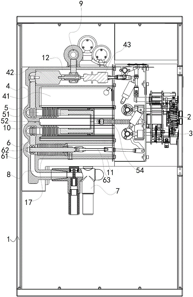
[0035] The present invention will be described in further detail below in conjunction with the accompanying drawings and specific embodiments.

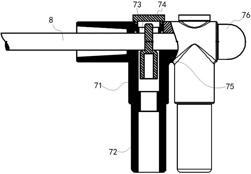
[0036] Such as Figure 1-7 As shown, the specific embodiment of the present invention is a 12kV current-carrying 1250A solid insulated switchgear, including a box body 1, a panel 13, a locking mechanism 3, a spring energy storage operating mechanism 2, a busbar seat 9, and an outgoing line insulating seat 7 , the middle part of the box body 1 is provided with an insulating square cylinder composed of an upper insulating base 12 and a lower insulating base 11, and the labyrinth of increasing the insulating creepage distance between the upper insulating base 12 and the lower insulating base 11 A polytetrafluoroethylene insulating board 14 is arranged in the groove, and a vacuum switch 4, a disconnector 5, a grounding switch 6, a bus bar seat 9, and an outgoing line insulating seat 7 are respectively arranged in the upper insulating base...


PUM


Abstract

The invention discloses a 12kV current-carrying 1250A solid insulation switchgear. The switchgear comprises a casing, the central portion of the casing is provided with an insulation square barrel, and the insulation square barrel is internally provided with a vacuum switch, an isolation switch and a grounding switch. The insulation square barrel is externally provided with a metal shielding grounding layer, and a spring energy storage operating mechanism and a locking mechanism are arranged at one side of the insulation square barrel and are respectively in driving connection with the vacuum switch, the isolation switch and the grounding switch. According to the invention, by use of a through cluster bus structure, no matter wiring is performed at the front end or the rear end of a wire inlet and outlet system, a sufficient conductive cross section can be guaranteed, by use of a watchband contact finger technology, contacts are uniformly distributed, the conductor length is reduced, the overall loop resistance is reduced, the problem of non-uniform conduction in heavy-current electric contact is avoided, and pressing looseness caused by temperature distortion of a conductor and heating malicious deformation further caused therefrom are solved. The rated current grade of a 12kV solid insulation switchgear can reach 1250A.

Description

technical field [0001] The invention relates to the field of power transmission and distribution switch cabinets, in particular to a 12kV current-carrying 1250A solid insulation switch cabinet. Background technique [0002] The solid insulated ring network cabinet is a combination of three technologies: insulated busbar, combined unit miniaturization, and external solid sealing. The switch and high-voltage live parts are sealed and encapsulated with solid insulating materials such as epoxy resin. It is a new type of power distribution equipment that is mainly insulated from body to ground and phase to phase, and the conductive or semi-conductive shielding layer on its outer surface is reliably grounded. It is generally used by the State Grid and China Southern Power Grid. [0003] With the popularization and application of domestic solid insulation cabinets in recent years, some of them have replaced expensive imported solid insulation cabinets, and have made indelible contr...

Claims


Application Information

Patent Timeline
IPC IPC(8): H02B13/00H02B1/20H02B1/04
CPCH02B1/04H02B1/20H02B13/005H02B13/01
Inventor 张增起曾锦河龙捷峰刁庆宪
Owner GUANGDONG PURLUX ELECTRIC
Learn More