
Photo-thermal composite curing 3D printing device and hook face in-situ printing method thereof

A 3D printing and light-curing technology, which is applied in medical science, prosthesis, additive processing, etc., can solve the problems of process pain, low material utilization rate, and no customized skin size and shape, so as to achieve less manual operation and increase Controllable, wide-ranging effects

Active Publication Date: 2016-08-24
XI AN JIAOTONG UNIV
View PDF4 Cites 18 Cited by
  • Summary
  • Abstract
  • Description
  • Claims
  • Application Information

AI Technical Summary

Problems solved by technology

[0004] Taking skin printing as an example, according to the statistics of the US military, 10%-30% of injuries on the battlefield are skin injuries, and the disadvantage of existing artificial skin is that the size and shape of the skin are not customized according to the specific parts of the patient.
The surface shape of damaged parts of human skin is generally a curved surface with different unevenness. Therefore, although the flat artificial skin has a certain degree of elasticity, it is difficult for the artificial skin to completely cover the parts with large surface curvatures such as the neck and shoulders. fit
In addition, when performing artificial skin transplantation, repeated cutting and pruning are required, the utilization rate of materials is low, skin damage cannot be repaired immediately, and the treatment period for patients is long and the process is painful

Method used


Image

  • Photo-thermal composite curing 3D printing device and hook face in-situ printing method thereof
  • Photo-thermal composite curing 3D printing device and hook face in-situ printing method thereof
  • Photo-thermal composite curing 3D printing device and hook face in-situ printing method thereof

Examples


Embodiment example 1

[0054] Skin-like structure printing: use two nozzle systems. The material of photocuring process nozzle system is photocurable PEDGA solution, configuration method: dissolve PEDGA and photoinitiator in deionized water so that their concentrations are 5% (w / v)-25% (w / v) and 0.5% respectively (w / v)-2% (w / v). Control parameters: The frequency of the solenoid valve controller is 2Hz-10Hz, the step distance is 0.5-1mm, the movement speed is 2-10mm / s, and the air pressure of the pressure reducing valve is 0.01-0.1MPa. ; The printing material of the temperature curing process nozzle system is gelatin, and the concentration is 5% (w / v)-40% (w / v). Control parameters: heating layer temperature 24-28°C, syringe pump flow rate 0.5-2ml / min, step distance 0.2-0.5mm, movement speed 2-10mm / s. Photocurable hydrogels with a thickness of 0.1-1mm and gelatin materials with a thickness of 0.1-1mm can be printed on curved surfaces with uniform thickness.

Embodiment example 2

[0056] Cartilage-like structure printing: use photo-curing process nozzle system, printing material is photo-curing PEDGA solution, configuration method: dissolve PEDGA and photoinitiator in deionized water so that their concentrations are 25% (w / v)-50% ( w / v), 0.5% (w / v)-2% (w / v). Control parameters: The frequency of the solenoid valve controller is 2Hz-10Hz, the step distance is 0.5-1mm, the movement speed is 2-10mm / s, and the air pressure of the pressure reducing valve is 0.05-0.1MPa. The printed cartilage-like structure has undergone mechanical performance tests, and the deformation can reach 50%, which meets the mechanical performance requirements of cartilage.


PUM

PropertyMeasurementUnit
diameteraaaaaaaaaa
diameteraaaaaaaaaa
thicknessaaaaaaaaaa

Abstract

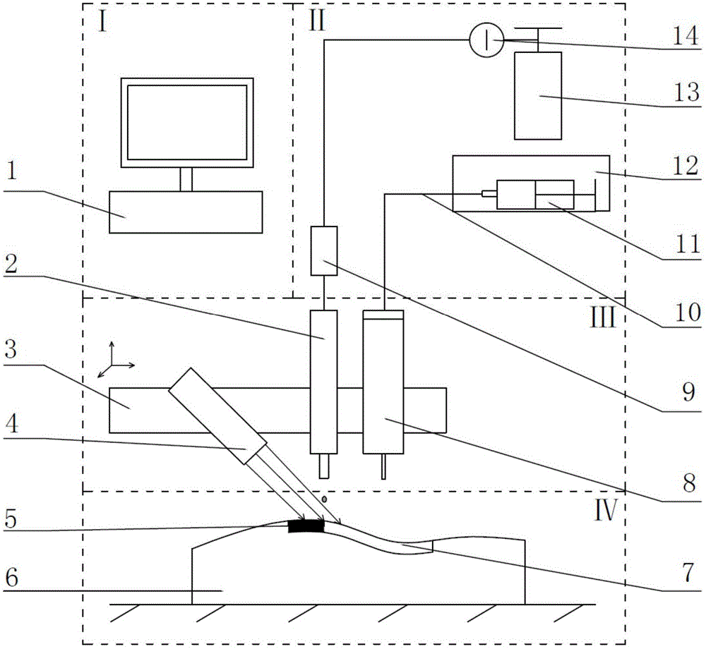
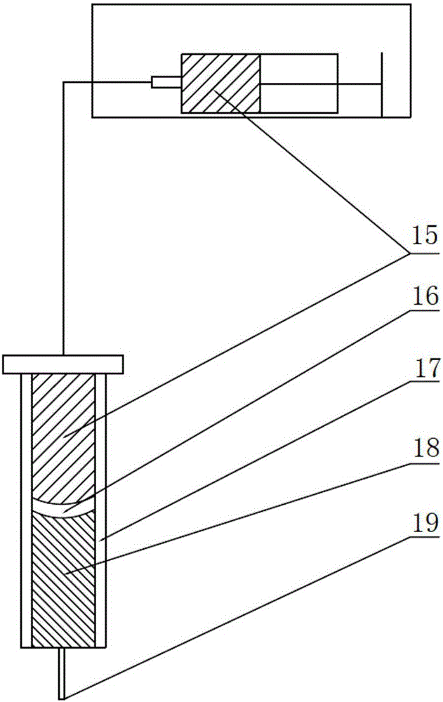
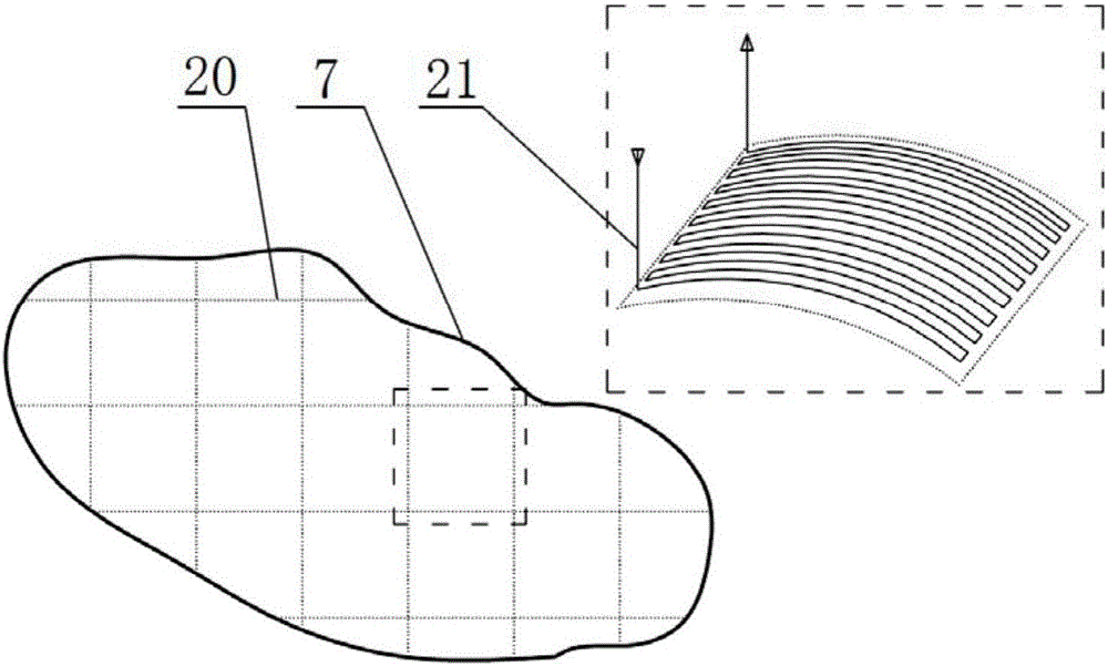
The invention discloses a photo-thermal composite curing 3D printing device and a hook face in-situ printing method thereof. The photo-thermal composite curing 3D printing device is composed of two sprayer systems, a three-dimensional motion platform, two feeding devices and a computer. Furthermore, the two sprayer systems include a photo-curing forming sprayer system and a temperature curing forming sprayer system, and collaborative printing of two forming technologies can be achieved. A hook face in the hook face in-situ printing method refers to printing on the hook face through a hook face layering method different from a traditional 3D printing plane layering method, and in-situ printing refers to direct printing at the artificial limb hook face defect position. A defect three-dimensional model is established by scanning the artificial limb hook face defect, a printing path is generated according to the size and shape of the defect, accordingly, sprayers are controlled to conduct three-axis linkage, the sprayers move along the defect face, and in-situ printing is finished. Furthermore, the device and method can be used for studying in the aspect of a hook face in-situ printing type skin structure and a cartilage-like structure.

Description

Technical field: [0001] The invention belongs to the intersecting field of mechanical automation, biotechnology and tissue engineering, and specifically relates to a photothermal composite solidification 3D printing device and a curved surface in-situ printing method thereof. Background technique: [0002] With the development of 3D printing technology, its application in the field of bioengineering has been paid more and more attention. Therefore, 3D printers used in bioengineering are gradually coming out. The existing dual-nozzle printing equipment basically adopts the same process, but only increases the number of nozzles, but cannot realize the collaborative printing of different molding process materials, which cannot meet the gradually developing needs of bioprinting. [0003] In traditional 3D printing, the model is layered in the horizontal plane to achieve layer-by-layer printing. During the printing process, only the XY two-axis movement needs to be realized in ...

Claims


Application Information

Patent Timeline
Patent Type & Authority Applications(China)
IPC IPC(8): B29C67/00A61F2/00B33Y10/00B33Y30/00B33Y80/00
CPCA61F2/00B33Y10/00B33Y30/00B33Y80/00
Inventor 连芩李晓于汉晨李志朝李涤尘刘亚雄贺健康
Owner XI AN JIAOTONG UNIV
Learn More