Multifunctional residual oil catalytic cracking method and device

A catalytic cracking device and catalytic cracking technology are applied in the fields of petrochemical industry and resource utilization, which can solve the problems of low catalyst oil ratio failing to meet the optimization requirements, increase of coke generation rate, and increase of coke generation rate of the device, so as to avoid unfavorable catalysts. Influence, avoid coking of settler, improve the effect of conversion capacity

Inactive Publication Date: 2016-08-24
刘英聚
View PDF0 Cites 0 Cited by
  • Summary
  • Abstract
  • Description
  • Claims
  • Application Information

AI Technical Summary

Problems solved by technology

At present, there are generally two problems in the heavy oil catalytic cracking riser reactor: 1. The catalyst-oil ratio is too low to meet the optimization requirements, and the catalytic activity of the catalyst is low during the catalytic reaction process. The catalytic activity of the 1/3 length above the heavy oil nozzle is only 1 of the initial activity. /2, the catalyst activity at 1/2 length is less than 1/3 of the initial activity, and the 1/2 length behind the riser is carried out under low catalyst activity, which seriously deviates from the optimal reaction conditions
2. The temperature at the bottom of the riser reactor is 20-30°C higher than the outlet temperature, and the wax oil raw material can meet the requirements. However, the boiling point of the heavy raw material oil is greatly increased, so that most of the heavy oil cannot be vaporized, and it ...

Method used


Image

  • Multifunctional residual oil catalytic cracking method and device
  • Multifunctional residual oil catalytic cracking method and device
  • Multifunctional residual oil catalytic cracking method and device

Examples


Embodiment Construction

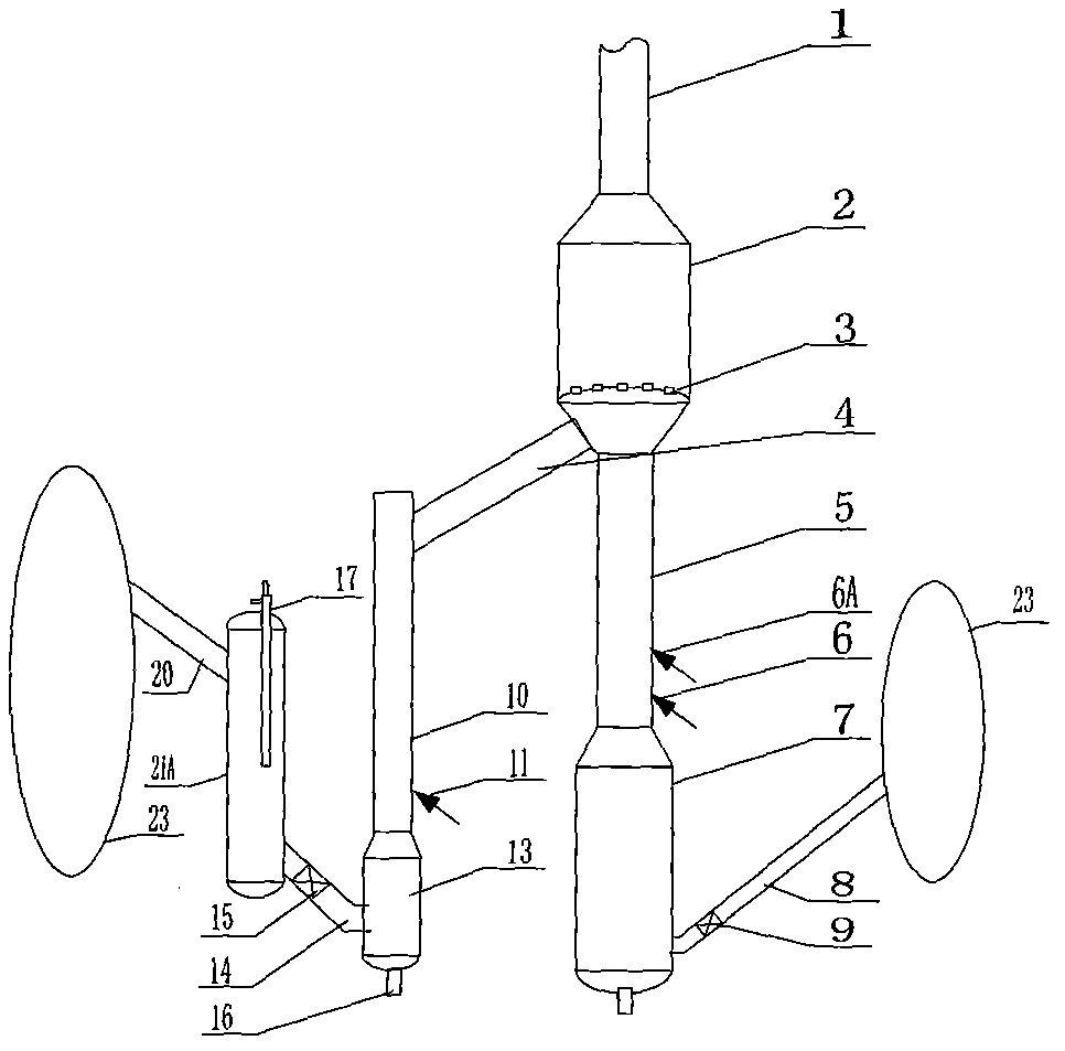
[0026] See figure 1 , the lower part of the main riser 5 is provided with a residual oil nozzle 6 and a refining oil nozzle 6A, the lower end is connected with the upper end of the main pre-lifter 7, and the upper end is connected with the lower end of the fast bed 2; the fast bed 2 is provided with a distributor 3, and its upper end is connected with the outlet The lower end of the tube 1 is connected. The lower part of the main regenerant pipe 8 is provided with a main regeneration slide valve 9 , its lower end is connected with the main pre-lifter 7 , and its upper end is connected with the regenerator 23 . The lower part of the auxiliary riser 10 is provided with a gasoline nozzle 11, the upper end is connected with the lower part of the rapid bed 2 through the connecting pipe 4, and the lower end is connected with the upper end of the auxiliary lifter 13, and the lower part of the auxiliary riser 13 is provided with a dry gas nozzle 16. The cooler 21A is provided with a ...


PUM


Abstract

The invention discloses a multifunctional residual oil catalytic cracking method and belongs to the technical field of petrochemical engineering and resource utilization. The method comprises the steps of regenerant and residual oil feeding, residual oil and regenerant mixing, vaporization, cracking and conversion. The method is characterized in that a high-activity low-temperature catalyst is introduced to the middle of a main reactor to achieve catalyst activity improvement and temperature reduction of the rear portion, and then hydrogen transfer, isomerization and aromatization of the rear portion are promoted; furthermore, the catalyst to oil ratio of the front portion and the temperature of the feeding stage are increased, so that initial cracking and vaporization of residual oil are promoted and high-temperature short-contact time cracking is achieved; an auxiliary reactor is arranged to guide a regenerant from a regenerator to be lifted by gasoline, so that cracking conversion reaction is conducted, and a high-activity spent catalyst which is 300-550 DEG C is conveyed to the middle of the main reactor. The invention further provides a residual oil catalytic cracking device comprising the main reactor and the auxiliary reactor for realizing the method. By the adoption of the method and device, residual oil conversion capacity can be improved remarkably, gasoline quality can be improved, and the yield of propylene, gasoline and light aromatics is high.

Description

technical field [0001] The invention belongs to the technical fields of petrochemical industry and resource utilization, and in particular relates to a multifunctional residual oil catalytic cracking method and device. Background technique [0002] With the increasing development of petroleum resources, the crude oil is getting heavier and heavier, and the feedstock for catalytic cracking is also getting heavier. The catalytic cracking process is a process in which heavy oil undergoes a gas-solid catalytic cracking reaction on a catalyst to generate light oil. The heavy raw oil in the catalytic cracking unit enters the bottom of the riser reactor after being atomized, and firstly undergoes initial cracking and vaporization of the heavy raw oil in contact with the high-temperature regeneration agent, and then the gas-solid catalytic cracking reaction occurs, and the reaction oil gas and the regeneration agent are converted from The outlet of the riser reactor flows out, and ...

Claims


Application Information

Patent Timeline
IPC IPC(8): C10G51/02
Inventor 刘英聚
Owner 刘英聚
Why Eureka
Try Eureka