Chemical heat washing process equipment and treatment technology for thick oil and oil sludge oil field wastes

A technology of oilfield waste and treatment process, which is applied in the field of oilfield waste heavy oil sludge chemical thermal washing process equipment and treatment process, which can solve the problems of extended waste transportation distance, drilling production cost pressure, and extended treatment time period. Achieve the effects of moderate automation control, low equipment operation noise, and convenient operation and management

Inactive Publication Date: 2016-08-31
北京华创天宇能源科技有限公司
View PDF7 Cites 3 Cited by
  • Summary
  • Abstract
  • Description
  • Claims
  • Application Information

AI Technical Summary

Problems solved by technology

[0002] In this field, the main problems are that the construction period of the station is long, the treatment of waste is not thorough enough, and it cannot be migrated with the change of the drilling block, which causes the waste to be transported to a longer distance, increases the transportation cost, prolongs the processing time period, and cannot meet the needs of drilling. Requirements for production relocation
[0003] Disadvantages of treatment while drilling for a single well: the treatment volume is not concentrated enough, and the treatment equipment while drilling cannot give full play to its performance, resulting in high unilateral cost of waste treatment, which puts pressure on drilling production costs

Method used


Image

  • Chemical heat washing process equipment and treatment technology for thick oil and oil sludge oil field wastes
  • Chemical heat washing process equipment and treatment technology for thick oil and oil sludge oil field wastes
  • Chemical heat washing process equipment and treatment technology for thick oil and oil sludge oil field wastes

Examples


Embodiment

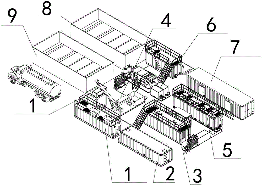
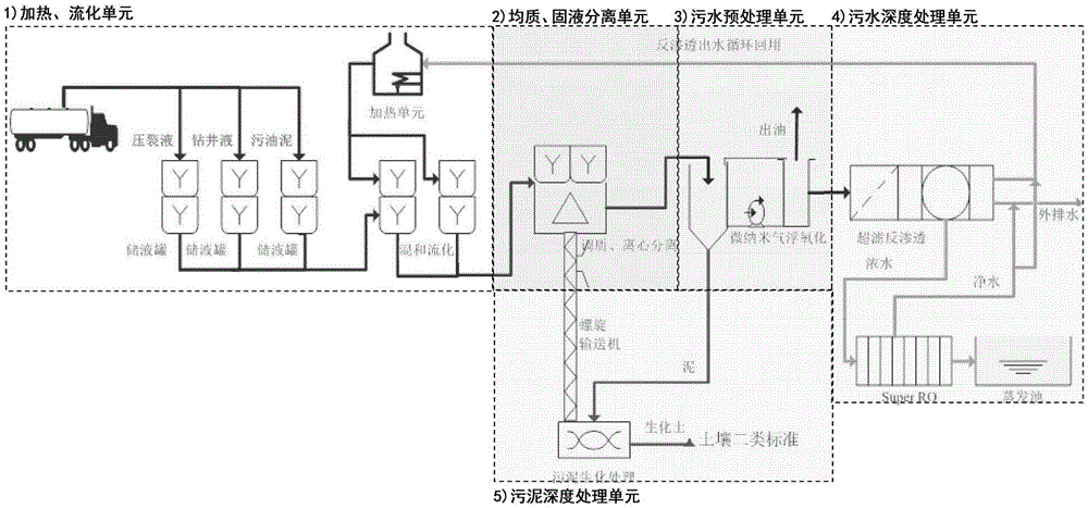
[0063] Heating and sludge fluidization unit

[0064] Select a special storage tank according to the incoming materials, and select a heating unit module and a fluidization unit module for early sludge fluidization and degreasing treatment.

[0065] Oilfield waste (fracturing fluid, drilling fluid and oil sludge) is sorted and stored after incoming materials;

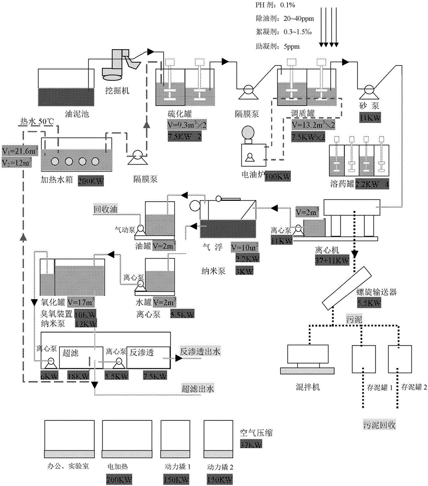
[0066] The heating unit of the power distribution heat conduction oil furnace is used to heat the thick oil sludge that needs high-temperature fluidized oil washing;

[0067] According to the predetermined fluidization ratio and fluidization temperature, put oil sludge and hot water into the fluidization tank for fluidization operation.

[0068] The output from the fluidized tank enters the next process unit for conditioning and separation treatment.

[0069] Fluidization of thick oil sludge and separation of oil, mud and water by hot oil washing process;

[0070] High-efficiency micro-protein surfactant degreaser is ...


PUM


Abstract

The invention provides chemical heat washing process equipment and a treatment technology for thick oil and oil sludge oil field wastes. The chemical heat washing process equipment comprises a heating and fluidization unit, wherein the heating and fluidization unit comprises a plurality of liquid storage tanks, a fluidization reaction tank and a heating unit, the liquid storage tanks are connected with the fluidization reaction tank, the fluidization reaction tank is connected with a homogenizing and solid-liquid separation system, the homogenizing and solid-liquid separation system comprises a blending tank and two centrifugal machines and is connected with a sewage pre-treatment unit, the sewage pre-treatment unit comprises an ozone micro-nano advanced oxidation device and an air floatation device and is connected with a sewage deep treatment unit, the sewage deep treatment unit comprises an ultrafiltration reverse osmosis device and an evaporation tank, both the homogenizing and solid-liquid separation system and the sewage pre-treatment unit are connected with a sludge deep treatment unit, the sludge deep treatment unit is connected with the homogenizing and solid-liquid separation system by virtue of a spiral conveyor, and the sludge deep treatment unit comprises a sludge biological treatment tank.

Description

technical field [0001] The invention relates to the technical field of petroleum equipment, in particular to chemical heat washing process equipment and a treatment process for oilfield waste heavy oil sludge. Background technique [0002] In this field, the main problems are that the construction period of the station is long, the treatment of waste is not thorough enough, and it cannot be migrated with the change of the drilling block, which causes the waste to be transported to a longer distance, increases the transportation cost, prolongs the processing time period, and cannot meet the needs of drilling. Requirements for production relocation. [0003] Disadvantages of WD treatment for a single well: the treatment volume is not concentrated enough, and the WD equipment cannot fully exert its performance, which leads to high unilateral cost of waste treatment and puts pressure on drilling production costs. Contents of the invention [0004] Aiming at the deficiencies i...

Claims


Application Information

Patent Timeline
Patent Type & Authority Applications(China)
IPC IPC(8): C02F9/14C02F11/00C02F11/14E21B21/01E21B41/00C02F103/10
CPCC02F1/02C02F1/04C02F1/24C02F1/38C02F1/40C02F1/441C02F1/444C02F1/72C02F9/00C02F11/00C02F11/02C02F11/06C02F11/14C02F2103/10E21B21/01E21B41/005Y02W10/37
Inventor 白庆玺叶明袁球
Owner 北京华创天宇能源科技有限公司
Why Eureka
Try Eureka