
A multifunctional vacuum coating machine

A vacuum coating machine and coating machine technology, applied in vacuum evaporation coating, sputtering coating, ion implantation coating and other directions, can solve the problems of easy breakage of resistance wires, easy control, difficult heat dissipation, etc. Fast heating and good practicality

Active Publication Date: 2018-02-06
YONGYI GRP
View PDF4 Cites 0 Cited by
  • Summary
  • Abstract
  • Description
  • Claims
  • Application Information

AI Technical Summary

Problems solved by technology

[0005] By adopting the above-mentioned technical solution, since the inductance coil generates heat relatively quickly and the temperature is easy to control, the problem that the traditional resistance wire is easy to break is solved; and hot water can be added to the thermal insulation cavity of the diffusion pump body, so that the heat is not easily dissipated into the air, and the heat The loss is small, which can improve the heating efficiency and play the role of heat preservation; in addition, there is a layer of heat preservation layer between the chassis of the coating machine and the inductance coil, which can cooperate with the heat preservation cavity to have a double heat preservation effect, and the mosquito repellent device has the effect of repelling mosquitoes. Make workers avoid mosquito bites when working overtime at night and improve work efficiency; the lighting device provides lighting at night, making it easy for overtime workers to operate; the monitoring camera monitors the working situation in real time, which is convenient for managers to manage and use; the structure design is reasonable and the structure is simple , Fast heating speed, high efficiency, energy saving, long service life, low energy consumption, easy to use, many functions, good practicability

Method used


Image

  • A multifunctional vacuum coating machine

Examples


Embodiment Construction

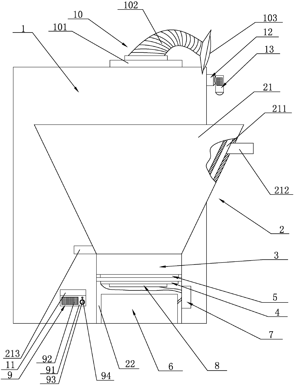
[0017] See figure 1 , The present invention discloses a multifunctional vacuum coating machine, comprising a coating machine body 1, a diffusion pump 2 is provided on one side of the coating machine body 1, and the diffusion pump 2 includes a diffusion pump body 21 and an integrated diffusion pump body 21 The diffusion pump base 22 is provided with a heat preservation cavity 211 in the wall surface of the diffusion pump body 21, and the upper end of the diffusion pump body 21 is provided with a water filling port 212 communicating with the heat preservation cavity 211, and the lower end of the diffusion pump body 21 is provided with The water outlet 213 connected with the heat preservation cavity 211; the diffusion pump base 22 is fixedly provided with a coating machine chassis 3, the coating machine chassis 3 is filled with diffusion pump oil, and the bottom of the coating machine chassis 3 is provided with an inductance coil 4 A layer of heat preservation layer 5 is provided ...


PUM


Abstract

The invention discloses a multifunctional vacuum coating machine which comprises a coating machine body. A diffusion pump is arranged on one side of the coating machine body. A storage groove is formed in the lower end of the coating machine body. A mosquito repellent device is arranged in the storage groove in an embedded manner. An illumination device is fixedly arranged at the top of the coating machine body and comprises a lamp holder, a metal flexible conduit and an LED lamp. The lamp holder is connected with the upper end face of the coating machine body. The lower end of the metal flexible conduit is connected with the lamp holder, and the upper end of the metal flexible conduit is connected with the LED lamp. A support is fixedly arranged at the upper end of the coating machine body and fixedly provided with a monitor camera. A power line of the mosquito repellent device, a power line of the illumination device and a power line of the monitor camera are electrically connected with a power line of the coating machine body. According to the technical scheme, the multifunctional vacuum coating machine is reasonable in structural design, simple in structure, high in heating speed, low in energy consumption and convenient to use and has multiple functions.

Description

Technical field [0001] The invention relates to the technical field of coating equipment, in particular to a multifunctional vacuum coating machine. Background technique [0002] The traditional vacuum coating equipment diffusion pump heating is to use a relatively high power consumption resistance wire to bake the bottom of the vacuum boiler (diffusion pump) by burning red, thereby heating the heat transfer oil inside to increase the temperature inside the vacuum pump to achieve the equipment's work Claim. This heating method causes most of the heat to be dissipated into the air, resulting in a large amount of heat loss and making the working environment temperature higher. Although the production cost is low, there are still shortcomings: slow heating speed, easy wire breakage, large energy consumption, inconvenient use, single function, inconvenient operation for workers during overtime work at night, especially from April to August each year, there are particularly many mosq...

Claims


Application Information

Patent Timeline
Patent Type & Authority Patents(China)
IPC IPC(8): C23C14/56C23C14/00
CPCC23C14/00C23C14/56
Inventor 苏庆掌
Owner YONGYI GRP
Learn More