In-situ test system and method for mechanical properties of nano material

A technology of nanomaterials and in-situ testing, applied in the direction of scanning probe technology, instruments, etc., can solve the problems that samples cannot be manipulated and measured at the same time, it is difficult to achieve reliable fixation, microscopic observation with external field effect, etc., to achieve convenient real-time observation, Reliable fixation, small size effect

Inactive Publication Date: 2016-08-31
BEIJING UNIV OF TECH
View PDF8 Cites 9 Cited by
  • Summary
  • Abstract
  • Description
  • Claims
  • Application Information

AI Technical Summary

Problems solved by technology

However, these instruments can only measure a single aspect of nanomaterials, and cannot meet the functions of simultaneous manipulation and measurement of samples, as well as in-situ and dynamic observation. It is difficult to achieve reliable fixation, external field application, and microscopic observation. Measurement

Method used


Image

  • In-situ test system and method for mechanical properties of nano material
  • In-situ test system and method for mechanical properties of nano material
  • In-situ test system and method for mechanical properties of nano material

Examples


example 1

[0085] Example 1: Application of the joint testing system of the present invention in in-situ three-dimensional topography imaging

[0086] The principle of three-dimensional topography imaging using this joint test system is the same as that of commercial AFM imaging. In the experiment, the probe 281 is the NSC11 probe of μmasch company, and its elastic constant is 3.0N / m. The standard AFM grating sample is selected as the sample, and its calibration size is 2 μm in cycle width and 200 nm in calibration height. Selecting this standard sample can realize the three-dimensional shape imaging function, and can also calibrate the displacement accuracy of the test system. Install the sample and probe 281 according to step 1.2 and step 1.3 respectively, and the topography of the obtained standard sample is shown in Figure 6 shown. The experimental research found that the period width measured by scanning the picture of the standard grating sample is 2.1±0.1μm, and the grid height...

example 2

[0087] Example 2: Application of the joint testing system of the present invention in the process of manipulating nanomaterials in situ

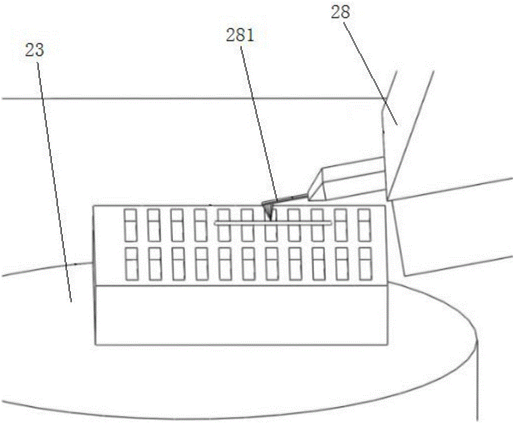
[0088] Different from the AFM scanning imaging mode, the manipulation and testing functions of the scanning probe testing unit 2 are realized by closing the Z-axis piezoelectric ceramic 233 feedback. In the imaging mode, the probe 281 is in contact with the sample, and the expansion and contraction of the Z-axis piezoelectric ceramic 233 is adjusted in real time through signal feedback, so that the probe 281 and the sample always maintain a certain relative height to maintain a certain physical quantity related to the distance between the needle tip and the sample. . In the manipulation and test mode, the feedback of the displacement of the Z-axis piezoelectric ceramic 233 is turned off, so that when the needle tip moves, it can directly collide with the sample to generate an interaction force.

[0089] Taking the planar movement arrangement ...

example 3

[0090] Example 3: Application of the combined testing system of the present invention in the in-situ three-point bending test of silver nanowires

[0091] Dilute the silver nanowires with uniform thickness and typical five-twin structure with alcohol solution and ultrasonically oscillate to disperse them evenly, then drop them onto the silicon wafer with etched microgrooves with a dropper, and wait for the alcohol to After the solution volatilizes, part of the nanowires are suspended across the two ends of the etching groove, and the contact parts are bonded together by adhesion, such as Figure 4 shown. The probe 281 selected for the in-situ three-point bending test is a commercial μmasch probe, the elastic constants are 3.5 N / m (NSC18), and the radius of curvature of the tip is 10 nm. Install the prepared sample and probe 281 according to steps 1.2 and 1.3 respectively, and perform an in-situ three-point bending test.

[0092] The study found that for silver nanowires with...


PUM


Abstract

The invention provides an in-situ test system for mechanical properties of a nano material. The in-situ test system comprises a scanning electronic microscope, a scanning probe test unit, a control unit and a computer; the scanning probe test unit comprises a base, an adjusting table arranged at one side of the upper surface of the base, and a measuring mechanism arranged at the other side of the upper surface of the base; the scanning electronic microscope comprises an electron microscope pole shoe, and the adjusting table is provided with a sample table, an X-axis adjusting apparatus, a Y-axis adjusting apparatus and a Z-axis adjusting apparatus; the measuring mechanism comprises a laser light path adjusting apparatus, a probe foundation support arranged on the base, and a probe arranged on the probe foundation support, the probe is positioned below the electron microscope pole shoe, and the laser light path adjusting apparatus is used for collimating and focusing laser. By adopting the in-situ test system and the in-situ test method, an acting process of the scanning probe and a sample and an evolution process of a sample microstructure under a physical mechanical function of an external field in the test process can be actually observed in site, and micro images of a series event and mechanical property test data are transmitted to a computer.

Description

technical field [0001] The invention relates to the technical field of microstructure performance testing equipment, in particular to an in-situ testing system and method for mechanical properties of nanometer materials. Background technique [0002] In the progress and continuous development of nanoscience and technology, two types of scientific instruments have played an important role in promoting, one is the electron microscope with the electron beam as the probe, represented by the transmission electron microscope (TEM) and the scanning electron microscope ( SEM); another type is a scanning probe microscope (SPM) with a solid tip as a probe, representatively scanning tunneling microscope (STM) and atomic force microscope (AFM). [0003] However, with the rapid development of micro-nano devices and the approach to the nanometer limit in scale, how to characterize micro-nano scale materials, structures and devices under the action of external fields (such as electric fiel...

Claims


Application Information

Patent Timeline
Patent Type & Authority Applications(China)
IPC IPC(8): G01Q30/02G01Q30/04
CPCG01Q30/02G01Q30/04
Inventor 张跃飞王晋马晋遥
Owner BEIJING UNIV OF TECH
Why Eureka
Try Eureka