
Regeneration amplifier with first pulse self-inhibition function

A regenerative amplifier and self-inhibiting technology, which is applied to lasers, phonon exciters, laser components, etc., can solve problems such as inapplicability and increase system complexity, so as to prolong service life, improve laser processing effect, and have a wide range of applications Effect

Active Publication Date: 2016-09-07
DAHENG NEW EPOCH TECH
View PDF3 Cites 5 Cited by
  • Summary
  • Abstract
  • Description
  • Claims
  • Application Information

AI Technical Summary

Problems solved by technology

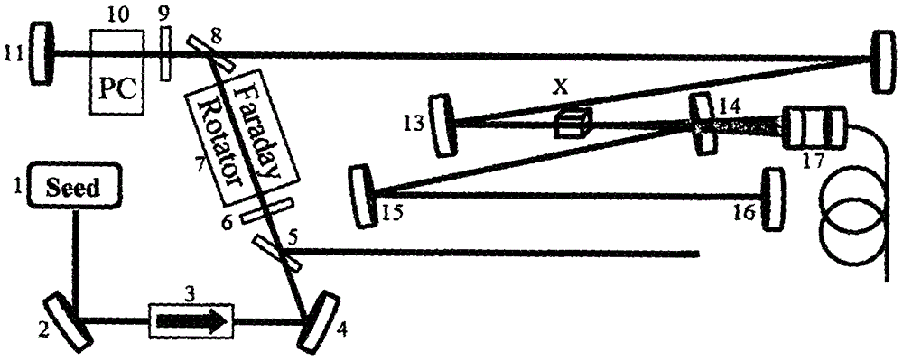
However, this scheme has obvious defects: first, this scheme is only suitable for regenerative amplifiers whose gain crystals are birefringent crystals; second, due to the birefringence effect, the separation angle of ordinary light and extraordinary light is very small, and it takes a long optical path to be clearly separated. Therefore, this scheme is not suitable for regenerative amplifiers with short cavity lengths; thirdly, this scheme adds several additional optical elements, which increases the system complexity

Method used


Image

  • Regeneration amplifier with first pulse self-inhibition function
  • Regeneration amplifier with first pulse self-inhibition function
  • Regeneration amplifier with first pulse self-inhibition function

Examples


Embodiment 1

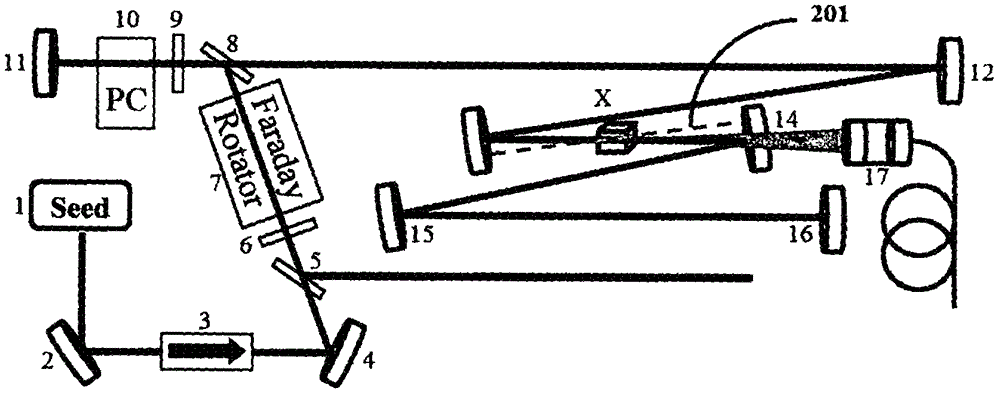
[0034] figure 2 Shown is a laser regenerative amplifier with the first pulse suppression function. The laser pulse output from the seed source 1 passes through the isolator 3, the wave plate 6, and the rotator 7, and the polarization direction is rotated by 90°. into the regeneration cavity. At this time, the electro-optical switch element 10 is pressurized, and its combination with the wave plate 9 rotates the polarization state of the incident laser light by 90°. When the laser light returns to the polarization beam splitting element 8, it passes through the element, and the laser light is locked in the cavity to go back and forth. The laser travels back and forth to the gain crystal X multiple times in the cavity, and the pulse energy is gradually increased. Then the voltage on the electro-optic switch 9 is changed again, and its combination with the wave plate 8 changes the polarization state of the intracavity laser again. The laser light is reflected from the polarizat...

Embodiment 2

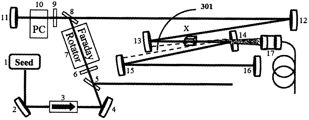
[0037] image 3 Shown is another laser regenerative amplifier with first pulse suppression. The difference from Embodiment 1 is that when the regenerative chamber stops working, parasitic oscillations are generated between the cavity mirror 13, the gain crystal X and the cavity mirrors 14 and 15 (301). Likewise, parasitic oscillations prevent crystal saturation, suppress first pulses, and do not affect output power and energy during normal operation.


PUM


Abstract

The invention discloses a regeneration amplifier with a first pulse inhibition function. The regeneration amplifier comprises a seed source, a pumping source and a regeneration amplification resonant cavity, wherein the cavity comprises elements of a gain medium, a controllable electro-optic switch, wave plates and the like. When a regeneration cavity does not work, parasitic oscillation can be generated between two or multiple lenses in the cavity; and inverted particles in the gain medium are consumed, so that saturation of the gain medium is avoided. When the regeneration cavity returns to work, the first pulse which is introduced into the regeneration cavity to be amplified does not obtain the gain which is obviously higher than that of the subsequent pulse; and the first pulse effect in an output pulse sequence of an amplifier is inhibited. No addition of the element in the first pulse inhibition process is achieved; the scheme is simple; and the cost is low. Furthermore, the regenerative amplifier is wide in application range and can be applicable to gain crystal with / without a birefrigent effect and a long / short regeneration cavity regeneration amplifier; through first pulse inhibition, relatively good output pulse uniformity can be obtained; meanwhile, vulnerable elements in the cavity are protected; the service lifetime of a laser device is prolonged; and the laser processing effect is improved.

Description

technical field [0001] The invention belongs to the field of ultrafast lasers and relates to a laser regenerative amplifier. Background technique [0002] As an important processing tool, laser has shown its unique advantages in the field of industrial processing. As an important branch of the laser processing field, laser fine processing is widely used in the fields of flexible circuit board manufacturing, wafer cutting, cardiovascular stent and solar cell manufacturing, etc. These fields have extremely high requirements for processing accuracy. Minimizing heat diffusion during machining is a key method to improve machining accuracy. A large number of research results show that ultrashort pulse laser with extremely short pulse duration can effectively reduce thermal diffusion, reduce the pulse energy and average power required for processing, and achieve good processing results. [0003] A cavity-empty laser with a pulse width in the order of nanoseconds and a repetition ...

Claims


Application Information

Patent Timeline
Patent Type & Authority Applications(China)
IPC IPC(8): H01S3/11
CPCH01S3/11
Inventor 范海涛常亮张翼
Owner DAHENG NEW EPOCH TECH
Learn More